INRIA home page
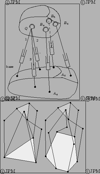
Manipulateurs
parallèles découplés. En haut le robot
d'Innocenti: trois actionneurs permettent
de commander les translations du point

, les trois autres permettant
de commander les rotations autour de ce point, d'après Innocenti [
76].
En bas
certains des segments

du manipulateur
précédent sont remplacés par des segments de type

où la
première articulation est
motorisée, d'après Uchiyama [
134].
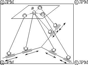
Le robot découplé Nabla 6: les trois
actionneurs prismatiques horizontaux des segments intérieurs
permettent de commander la position de

alors que les trois
autres permettent de contrôler l'orientation de la plate-forme.
Des recherches sont en cours pour déterminer qui est l'inventeur de
cette architecture.
The decoupled Nabla 6 robot: the three horizontal linear
actuator enable to control the position of

, while the three
other one enable to control the orientation around

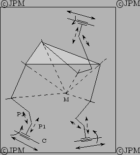
Le robot découplé de Jin: pour chaque jambe il y a deux
actionneurs qui motorisent l'articulation cylindrique C sur la base. Les
articulations prismatiques passives P1, P2 ont un axe perpendiculaire
à l'axe de C. Partant de la plate-forme on trouve succesivement 2
rotoïdes dont les axes doivent se couper au point M. En
actionnant uniquement les R des cylindriques on obtient un mouvement de
rotation de la plate-forme. En
actionnant uniquement les P des cylindriques on obtient un mouvement de
translation de la plate-forme [
78].
On the base we have an actuated cylindrical joint C. Then we have two
prismatic passive joint P1, P2 whose axis are perpendicular to the
axis of C. From the platform we have two revolute joints whose axis
intersect at M. By actuationg the R joint of the C joint we have a
rotation of the platform. If we actuate only the P joint of C we get
translation of the platform
Ce robot est constitué d'un robot parallèle
plan de type

surmonté d'un robot spatial de type

[
154]
This robot is constituted of a planar parallel robot of type

topped by a spatial

robot
Une variante de la plate-forme de Stewart [
71]
A variant of the Stewart platform
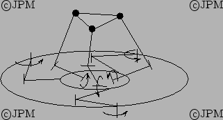
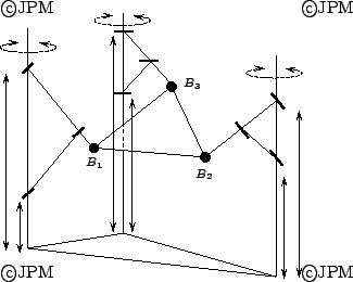
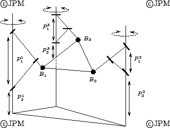
Le robot Tri-Scott: le mécanisme de Scott et la rotation autours des
mâts fait que les points Bi se
déplacent dans un plan sous l'action des actionneurs

. L'actionnement combiné de ces 3 actionneurs conduira à
des mouvements plans de la plate-forme. Les autres orientations de la
plate-forme et son altitude seront alors contrôlées par les actionneurs

[
182]
The Scott mechanism used in this robot is such that a motion of the

prismatic actuators leads to a planar motion of the platform
while the prismatics actuators will allow to control its orientation.
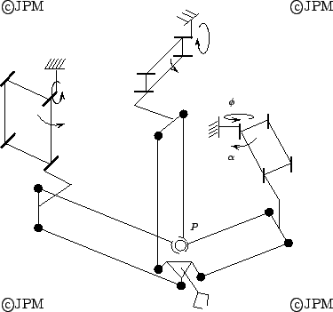
Le POLMAN-6: la commande des angles

des parallélogrammes
permet de commander la position du point P alors que les angle

permettent de commander les orientations autour de P [
126]
Control of the angle

allows to change the location of P while
the

's allows to control the orientation around P
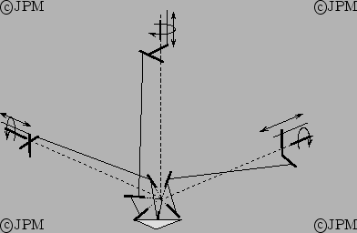
Le POLMAN-3x2, une variante du POLMAN6 la commande des rotations
proches de la base permet de contrôler les orientations autour du
point d'intersection des axes [
124].
Control of the rotation close to the base
allows to to control the orientation around the intersection point of
the axis.


 Next: Treillis articulés/Truss
Up: Manipulateurs à 6 degrés de liberté/6 DOF robots
Previous: Robots à chaînes exotiques/Robot with various kinematic chains
Next: Treillis articulés/Truss
Up: Manipulateurs à 6 degrés de liberté/6 DOF robots
Previous: Robots à chaînes exotiques/Robot with various kinematic chains