INRIA home page
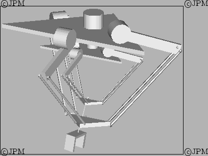
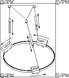
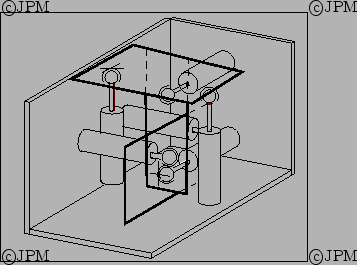
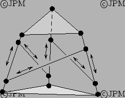
Le robot 2-delta de Lallemand constitué de deux robots Delta
imbriqués, d'après [
58].
The 2-delta robot of Lallemand: it is constituted of two 3-dof delta
robot.
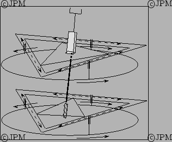
En combinant deux manipulateurs plans avec une ariculation
hélicoïdale on peut construire un
manipulateur
à 6 degrés de liberté, d'après Brodsky [
17].
Using two planar robots and an helical joint
it's possible to build a 6 d.o.f robot.
Le manipulateur de Han. Des mécanismes à 4 barres
sur la base, actionnés par des moteurs électriques, permettent de
déplacer les points d'articulation des segments, d'après Han [
61].
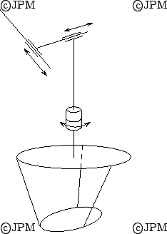
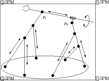
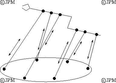
Le robot de Tahmasebi. Deux actionneurs rotatifs placés en

permettent de contrôler la position du point

.
Le prototype d'Alizade, d'après
Alizade [
4].
Le prototype de Janabi-Sharifi, d'après [
77].
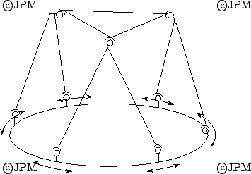
Des actionneurs rotatifs d'axe vertical permettent de commander les 6
d.d.l. de la plate-forme.
Ce robot
de type 6-RUS avait été commercialisé auparavant par Hexel sous le nom de
Rotobot [
15].
Revolute actuators with a vertical axis,
located on the base allow to control the 6 d.o.f. of the
platform. This 6-RUS robot has been previously commercialized by Hexel
under the name Rotobot [
15].
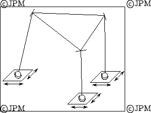
Le prototype de Tsai, d'après Tsai [
171]
Une variante du robot précédent, le TriPlanar [
115]
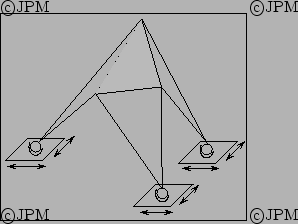
Le prototype de Kohli, avec des actionneurs
doubles, linéaire et rotatif, d'après Kohli [
89]
Kohli prototype with double linear-rotary actuator
Le prototype de Behi, avec des actionneurs
doubles, linéaire-linéaire, d'après Behi [
12].
Behi prototype with double linear-linear actuator
Une variante des robots de Behi et Kohli, le 3-CPR, au appelé le
Tetrahedral Tripod, où l'articulation passive
sur la plate-force est une rotoïde dont l'axe doit être
parallèle à l'axe de l'articulation C [
40].
A 3-CPR variant of Behi and Kohli robot with a revolute joint on the
platform, whose axis must be parallel to the axis of the C joint on
the base.
Une structure de type 3-PRRS avec un actionnement du P et du
deuxième R en partant de la base [
131]. Un tel
actionnement peut être obtenu par un pignon pris entre 2
crémaillères [
129].
A 3-PRRS structure: the actuated joints are the P and the second R
starting from the base. This actuation may be obtained with a pinion
between two racks [
129].
Le robot à 6 degrés de liberté de Byun utilisant des chaines PPSP
d'après Byun [
20].
The 6 dof robot of Byun with three PPSP kinematic chains.
Un mécanisme à 6 degrés de liberté [
39] obtenu en actionnant les
deux côtés d'un parallélogramme: l'intérêt de ce mécanisme
est qu'il peut être équilibré à l'aide de ressorts.
A 6 DOF robot: the motion are obtained by rotating the two sides of
the parallelogramms: this mechanism can be balanced using springs.
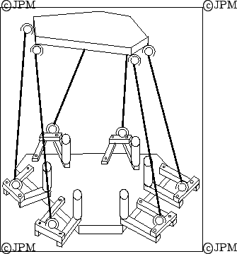
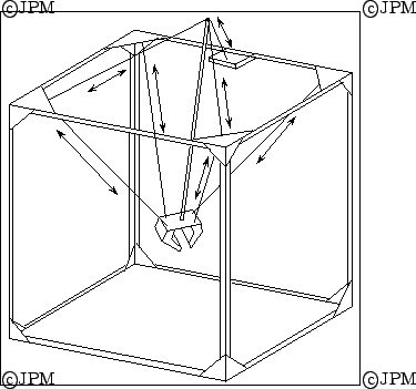
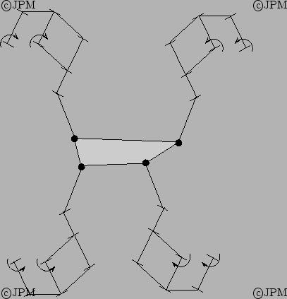
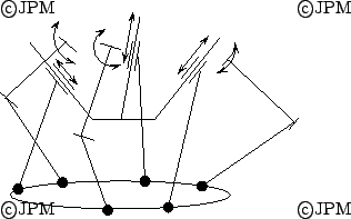
Un robot redondant avec 4 jambes. Les actionneurs sont placés sur
les axes des joints de Cardan. On a une rotoïde passive au milieu
de la jambe et chaque jambe est attachée à la plate-forme par une
rotule [
181]
A redundant robt with 4 legs. The actuated joints are the axes of the
U joint on the base. In each leg we have a passive revolute joint and
each leg is connected to the platform through a ball-and-socket joint
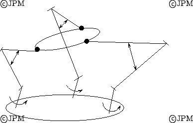
Le robot
Eclipse à 7 actionneurs: trois chariots actionnés
bougent sur un rail circulaire. Ils supportent 3 actionneurs
linéaires reliés par des articulations pivot à 3 barres, dont
une peut changer de longueur. Ces barres sont reliés a` la
plate-forme par des rotules [
155]Ryu.
The
Eclipse robot
with seven actuators mentioned by Ryu [
155]Ryu:
three carriages supporting stems
move on a circular rail, and on the stems are 3 linear actuators
supporting three revolute joints connected to fixed length links, one
of which is actuated. The
other ends of the links are connected to the moving platform through
ball-and-socket joints.
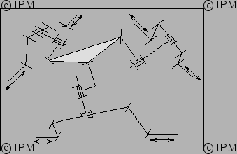
La version suivante de l'Eclipse, l'Eclipse II. Il a été
conservé les deux piliers circulant sur le rail circulaire fixe mais
le 3eme a été remplacé par un rail circulaire qui peut tourner
autour de l'axe vertical et sur lequel circule le chariot avec la
troisième jambe. Une singularité est obtenue lorsque le centre
d'une rotule est sur l'axe vertical. Pour éviter ce cas une des
rotules peut être placée sur un actionneur supplémentaire
(le robot aura alors 7 actionneurs)
représenté en pointillé sur la figure [
86]
The new version of Eclipse. The two beams circulating on the circular
rail has been kept but the third one has been substituted by a
circular rail that can rotate around a vertical axis. On this rail is
attached the third leg. The ball-and-socket joint connecting the third
leg to the platform may be actuated (dashed line)
to avoid singularity (hence the
robot will have 7 actuators).
Le robot SPACE de Beji [
14]. Les actionneurs sont sur un
des axes du joint de Cardan de la base et un actionneur prismatique
dans la jambe.
The SPACE robot: there is an actuated revolute joint in the U-joint
on the base and a prismatic actuator in the leg
2 manipulateurs
parallèles à câbles permettent d'obtenir un robot à
6 degrés de liberté, d'après Parushev [
133].
Two wire robots enabling to build a 6-dof robot
Le robot à câble Falcon destiné à l'assemblage
ultra-rapide (d'après [
82])
The Falcon ultra fast parallel robot for high speed assembly
Un robot hybride à câbles, d'après [
117].
An hybrid robot, part serial, part parallel with wires.
Dans ce robot un premier
module est constitué de deux plateaux reliés par 6 segments dont 3 ont
une longueur fixe (en traits épais)
et les 3 autres sont de longueur variable. Une structure
identique relie le plateau supérieur à
l'organe terminal, d'après Shahinpoor [
159].
Le robot "SMARTee". Le mécanisme différentiel
permet de commander deux degrés de liberté du premier segment de
chacune des trois chaînes, d'après Cleary [
31].
Une architecture de manipulateur parallèle,
proposée par Artigue, permettant
d'obtenir une matrice de raideur diagonale. Les actionneurs linéaires
sont liés de manière rigide à la base et comportent à leur
autre extrémité une rotule liée au plateau mobile
par une articulation glissière permettant les translations dans un
plan, d'après Artigue [
7].
Le prototype de Romiti. Il est constitué de 3
ensembles de motorisation. Dans chaque ensemble un double
parallélogramme plan
déplace une rotule, liée au plateau mobile, qui peut
se déplacer sur une glissière, d'après Romiti [
153].
Le "double tripode" de Merkle: les groupes de
3 actionneurs linéaire permettent de déplacer les points

dans l'espace, ce qui assure 5 degrés de liberté
à l'organe terminal. Un mécanisme d'entraînement à vis permet
d'assurer
la rotation de l'axe terminal autour de son axe,
d'après Merkle [
121].
Une variation du "tripode" de Merkle: l'organe terminal peut tourner
complétement autour de son axe, d'après Merkle [
121].
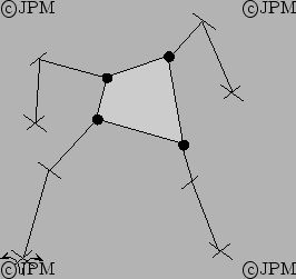
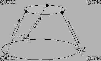
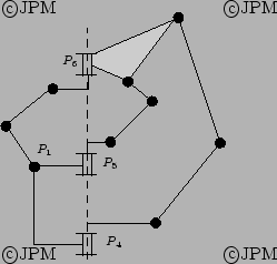
Un robot à 6 degrés de liberté proposé par Sarkissian. Les
axes des articulations rotoîdes de chaque chaîne sont parallèles
d'après Sarkissyan [
157].
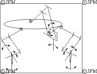
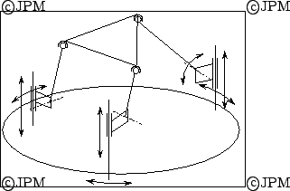
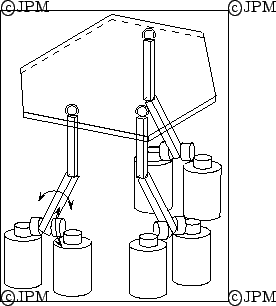
Un robot à 6 degrés de liberté proposé par Nagai pour un robot
ultra-rapide. Une jambe du robot est composé d'un parallélogramme
articulé avec deux actionneurs. A l'extrémité du
parallélogramme une articulation rotoïde passive connecte un
bras de longueur fixe à la rotule de la
platforme [
128]. L'utilité d'avoir 4 bras n'est pas
expliqué.
A fast 6-dof robot. Each leg is constituted of an articulated
parallelogram with 2 actuators. At the end of the parallelogram a
passive revolute joint connect a fixed length link to the
ball-and-socket joint of the platform. It is unclear why 4 legs are used.
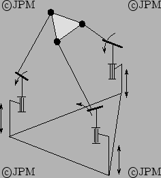
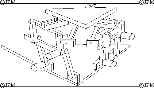
Un mécanisme à 3 jambes: le mouvement est
controllé par des actionneurs linéaires qui permettent de faire
varier l'angle entre les segments proche de la plate-forme et par des
actionneurs rotatifs qui font tourner les axes des
rotoïde sur la base [
108].
A mechanism with 3 legs
The linear actuator control the angle between the two links close to
the platform while the rotary actuator on the base change the
direction of the first revolute joint axis.
Un mécanisme à 3 jambes et seulement des articulations
rotoïdes (il est prévu pour une fabrication MEMS, une
technologie où les
articulations charnières sont
maîtrisées) [
11]
A 3-legged robot with only revolute joints: the robot is designed for
a possible use as a MEMS and in this domain hinge joint are mastered.
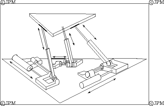
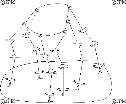
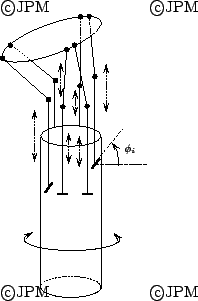
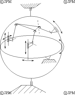
Le Cobot. Des roues sont au contact
d'un cylindre qui tourne en permanence et des actionneurs permettent
de modifier l'angle

entre les roues et le cylindre. Selon cet
angle les tiges montent ou descendent à une vitesse variable ce qui
permet de modifier la position de la plate-forme [
44].
Here the wheels are in contact with a rotating cylinder. Actuators
allow to modify the angle between the wheel and the cylinder axis.
The vertical velocity of the beam that are connected to the wheels
is a function of this angle and their control allows to modify the
pose of the platform.
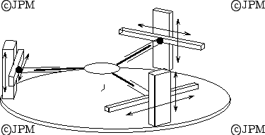
Un robot ` 6 d.d.l. mais seulement 2 jambes. Les rotules près de
la base sont entiérement actionnées et dans les jambes on a une
acticulation prismatique passive (qui peut être remplacée par une
rotoïde) [
176]
Here the ball-and-socket joints of the 2 legs are fully actuated and
in each leg we have a passive prismatic joint.
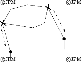
Un robot à 6 d.d.l. mais qui peut se transformer en robot à 3, 4,
5 ddl en deconnectant les articulations rotules des chaîne

[
178]
A 6 dof robot that may become a 3, 4, 5 dof robot by disconnecting the
S joints of the the

chains
Un robot dont la nature des degrés de liberté et leur nombre peut
changer. Ici les axes des articulations

sont alignés:
le robot à 2 ddl de type cylindrique. Mais si on utilise

pour
ne pas avoir les axes alignés on obtient un robot plan à 3
ddl [
42]
A robot whose number and nature of dof may change. Here the axis os
the joints

are aligned: we get a 2 dof robot with
cylindrical motion. Now by using

the axis of these joints may be
no more aligned and we get a planar 3 dof robot.
Un robot dérivé d'un 6-UPS en croisant les jambes (on peut
considérer qu'il s'agit aussi d'une variation de la plate-forme de
Stewart). On peut aussi placer l'ensemble des actionneurs sous la
base [
50].
A derivation of the 6-UPS robot, that may also be considered a
variation of the Stewart platform. The prismatic actuators may also be
located under the base.
Un robot à 3 jambes de type CC. La rotation du C près de la base
est contrôlée ainsi que la longueur des jambes [
48]
A robot with 3 legs, each leg having CC joints. The rotation of the
first C and the length of the leg are controlled.


 Next: Robots découplés/Decoupled robots
Up: Manipulateurs à 6 degrés de liberté/6 DOF robots
Previous: Robots à chaînes , /Robot with , kinematic chains
Next: Robots découplés/Decoupled robots
Up: Manipulateurs à 6 degrés de liberté/6 DOF robots
Previous: Robots à chaînes , /Robot with , kinematic chains