


Next: Interaction with the object
Up: How to execute the
Previous: Quit
Contents
Index
We recommend to use the ``multi 3D plot'' mode for computation and
visualization of isosurfaces, but this is the first implementation of
theses features and can still be used.
With the example defined by the ``ex_3d.desc'' description file, we push
now the ``3D'' button on the main menu and start the ``Isosurface mode.
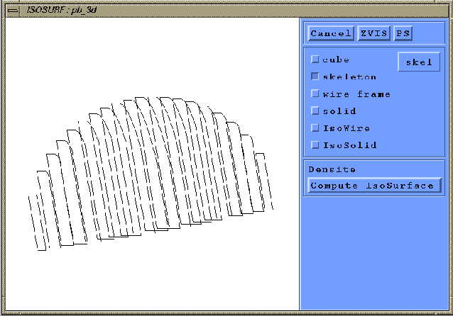
A working window appears (see figure 1.47), representing by
default the skeleton. Each components of this
working window are described below.
Figure 1.47:
3D Isosurface working window.
 |
Subsections
Robert Fournier
2002-09-13