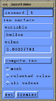
In the ``cur isosurf'' frame, push the ``add'' button. The name of the new defined isosurface appears as ``isosurf 1''. You can now set the toggle ``infos'' on, a new window titled ``isosurf infos'' appears (figure 1.29). With this window, you can change the name of the isosurface, the variable and the value use for its computation. The default variable name is the current ``value'' set in the working window when the isosurface was created, and the default value is the middle between the maximun and the minimun for this default variable.
You can use three toggles to choose if you want only to compute the mesh of the isosurface(``mesh''), to interpolate the current variable (``selected value'') at the mesh nodes, or to interpolate all the variables (``all values'').
When the isosurface computation is defined, press the ``set'' button, and ``compute cut''. The new computed isosurface can be visualized with the ``isos'' toggle on.
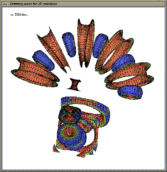
You can see on figure 1.30, the isosurface, for the current
example, of the variable named ``bulles'' for the value ![]() , colored
by the variable named ``sin_dist''.
, colored
by the variable named ``sin_dist''.