INRIA home page
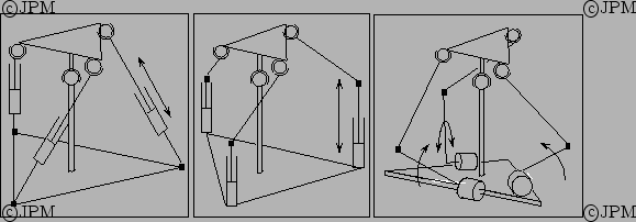
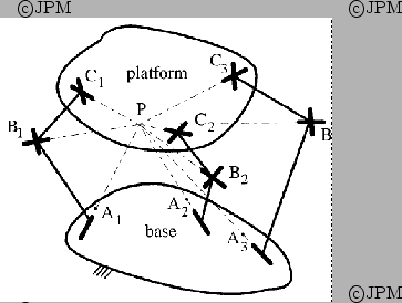
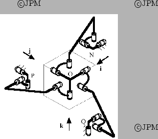
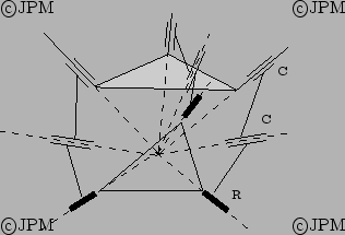
Différents poignets parallèles avec le
plateau mobile articulé sur une rotule placée sur un
mât central. Les chaînes parallèles sont du type

. Les joints de Cardan sont représentés
par un carré noir.
Les actionneurs linéaires sont représentés par

et les actionneurs rotatifs par un arc fléché.
Various parallel wrists with a central mast. A ball-and-socket joint
enable to have only rotation motion. The kinematic chains are
. Universal joints are represented by a black
square.
The linear actuators are represented by

while
revolue actuators are represented by arcs.
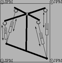
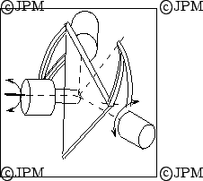
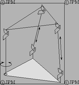
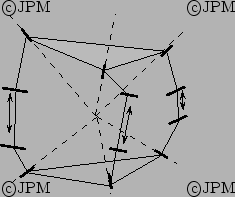
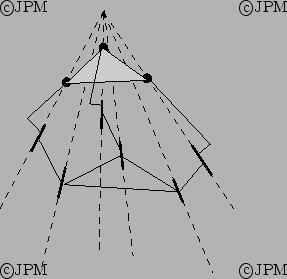
Le poignet de Hayward: quatre actionneurs
linéaires permettent d'orienter un plateau monté sur
rotule, d'après Hayward [
63].
The Hayward's wrist: 4 linear actuators enable to orient the
end-effector.
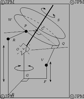
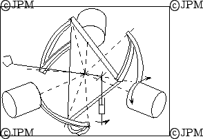
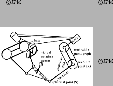
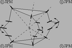
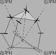
Le poignet de Agrawal. La rotation autour de

permet d'assurer la rotation complète du plateau supérieur

alors
que les translations de

assurent
les deux degrés de liberté en orientation restant, d'après Agrawal [
1].
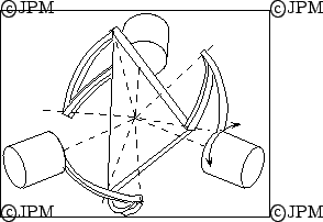
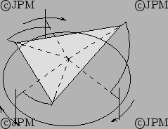
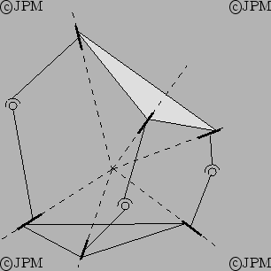
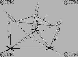
Le poignet sphérique
Agile Eye de Gosselin. Trois
chaînes sphériques sont utilisées avec des actionneurs rotatifs dont
les axes sont concourants au centre du plateau mobile, d'après
Gosselin [
55].
The spherical Agile Eye wrist: three spherical chains with rotary actuator are
used. All the axis joint of this mechanism intersect at a common
point.
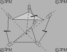
Une variante de l'
Agile Eye de Gosselin. Le quatrième
actionneur rotatif permet d'améliorer les capacités de rotation, d'après
Hess-Coelho [
67].
A variant of the Agile Eye wrist: the 4th revolute actuator
allows to improve the rotational capability.
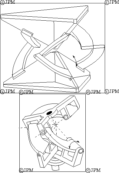
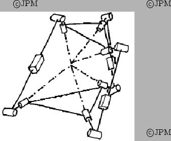
Les prototypes de poignet de Tesar. Les actionneurs
rotatifs et toutes les articulations ont leur axe concourant en un
point, d'après Tesar [
166].
Ube variante de poignet spherique: ici les articulations rotoïdes
proches de la base se déplace sur un rail circulaire [
10].
A variant of spherical wrist: here the rotoid joint close to the base
are moving on a circular rail.
Un poignet reposant sur une mécanisme sphérique
à 5 barres. Ce mécanisme est actionné par deux actionneurs rotatifs
placés sur les articulations liées à la base. La rotation autour
de l'axe

est obtenue par un actionneur placé sur cet axe, d'après Ouerfelli [
132].
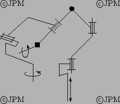
Le poignet de Cheng. Le mât central est
monté sur une articulation rotoïde actionnée et les deux
autres actionneur prismatiques permettent de commander les autres rotations
(d'après [
27])
Cheng wrist: the central mast lie on a rotoid actuated joint and the 2
others linear actuators enable to control the other 2 rotational DOF
Le robot ARGOS de Vischer, une variation habile du Delta [
172]
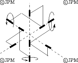
Un robot 3-UPU dans une configuration où les degrés de liberté
sont des rotations [
80], dessin de Bonev
A 3-UPU robot in a configuration where the 3 d.o.f are orientational.
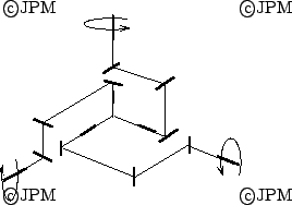
Un poignet 3-RUU [
33]. Certaines articulations
rotoïde ne bougeront quasiment pas (articulation
immobile [
64]).
Here some revolute joints will almost never move (idle pairs [
64])
Un poignet 3-RUU [
64] sans articulation immobile (here no
idle pairs).
Mais les U du 3-UPU peuvent être remplacés par le couple RR pour
obtenir un robot de type 3-RRPRR [
34].
The U joint of the 3-UPU may be substituted by a RR pair leading to a
3-RRPRR mechanism
Et les actionneurs P du 3-RRPRR peuvent être remplacés par un
actionneur R pour obtenir un mécanisme
3-(5R) [
34].
The P active joint of the 3-RRPRR may be substituted by a R joint to
obtain a 3-(5R) wrist
Les actionneurs P du 3-RRPRR peuvent être remplacés par une
articulation R pour obtenir, par exemple, un mécanisme
3-RSR [
35].
The P active joint of the 3-RRPRR may be substituted by a R joint to
obtain, for example, a 3-RSR wrist
A 3-RRS spherical wrist [
43]
A 3-CRU spherical wrist [
43]
A 3-UPC spherical wrist [
43]
A 3-CRC spherical wrist [
43]
A 3-RCC spherical wrist [
81]. It may also be declined as
3-CCR, 3-CRC.
Un exemple de poignet utilisant un joint homocinétique. Toutes les
articulations ont des axes parallèles ou perpendiculaires. Le joint
homocinétique est représenté par le carré
noir [
52].
An example of wrist with homokinetic joint. All joints have parallel
or perpendicular axis and the homokinetic joint is represented by the
black square.
Un poignet découplé composé uniquement de joint
rotoïde [
186]
A decoupled wrist with only revolute joints
Ici des chaînes de type

avec des axes
parallèles ou perpendiculaires et de dimension spéciales
permettent d'obtenir des translations [
51]
Here

chains with parallel or perpendicular axis
and special dimensions allows one to obtain translation


 Next: Manipulateurs à degrés de liberté complexes/Robots with complex DOF
Up: Manipulateurs à 3 degrés de liberté/3 DOF robots
Previous: Manipulateurs pour translations/Translation robots
Next: Manipulateurs à degrés de liberté complexes/Robots with complex DOF
Up: Manipulateurs à 3 degrés de liberté/3 DOF robots
Previous: Manipulateurs pour translations/Translation robots