Mariano Vázquez,
Alain Dervieux
INRIA Sophia - Antipolis, France
Bruno Koobus
University of Montpellier, France
INRIA Sophia - Antipolis, France
Bruno Koobus
University of Montpellier, France
Authors' e-mails:
Mariano.Vazquez@sophia.inria.fr
Alain.Dervieux@sophia.inria.fr
koobus@darboux.math.univ-montp2.fr
This web page is no more than a brief summary of the project. For the complete sources, please refer to the "Up-to-date publication's list" section and download the papers available, down below here.
A brief account and some results concerning the second stage of the project is found here:
and here, for the preliminary results of the POD based optimization:
Back to M. Vázquez Home Page.
Introduction:
This project is being carried out in INRIA Sophia-Antipolis (years 2002-2003). It is a French Ministries of Research and Transport Project, under the ``Research and Technological Innovation Network: Supersonic Aeronautical Research''. Its leader is Alain Dervieux, and Mariano Vazquez (INRIA Sophia-Antipolis) and Bruno Koobus (University of Montpellier, France) are his co-workers. The project also includes contributions from Francois Courty (INRIA Sophia-Antipolis). Airplanes Falcon and Supersonic Bussiness Jet "Supersonic Falcon" geometries are provided by Dassault Aviation.
Figure 1. The sonic boom. Sketch of near and
far field shock wave patterns of a
supersonic aircraft.
supersonic aircraft.
The project's goal is to optimize shapes in order to reduce its sonic boom (see [1] for an authoritative review on the sonic boom theory). The sonic boom is the ground shock signature produced by a body which moves at supersonic regime (see Figure 1). At this regime, any body can very likely develop a main shock wave which moves ahead of it at its (supersonic) speed. It propagates backwards and due to the very low air viscosity its effects can be noticed very far from the origin place, typically an aircraft. In fact, "noticed" is a very weak word to describe the sonic boom. It is a very strong explosive sound, completely sudden and unattended of dramatic environmental impact, which usually causes glass trembling and can produce structural damage to buildings if repeated. In fact, commercial supersonic flight in USA and Europe is prohibited. The Concorde confines its supersonic operations to overwater routes only. This effect is due to the fact that the rather complex near field pressure shock system that is formed below the planed and travels with him, when propagated downards through the athmosphere, coalesces, forming a steep N-wave in the ground (at about 15km for the Concord at cruise altitude).
A second stage in the project is the aeroelastic fluid-structure coupling. The aeroelastic deformations suffered by the wings in flight are taken into account in the optimization process. This is done by combining the aerodynamic sonic boom optimization scheme with an aeroelastic analysis of the resulting shapes at
each of the optimization iterations. This point is particularly interesting facing MDO (Multi-Disciplinary Optimization).
The results for the second stage, the coupled aeroelastic sonic boom optimization, are to appear in a future INRIA Report [e]. See a brief account and a "selected results gallery" here. A side effect of this research is a study of energy conservation issues in aeroelasticity, to appear as a future INRIA Report [f].
Another issues to be considered (in the next year 2003) is the simultaneous optimization for different regimes (transonic and supersonic), the multi-point optimization and a POD (proper order decomposition) based optimization scheme.
Project's sketch:
The project falls within the domain of optimal shape design. The shape is optimized by changing its form consequently to changes in a non-linear objective function, the cost, which depends on the actual flow and design variables. The set of design variables spans the parameters space where we look for the target shape. The main ingredients of our methodolgy are:
Euler compressible flowsThe flow equations solved are those of the Euler compressible flows, which admits solutions with shock waves. As we have seen below, they are the cause for the sonic boom. The flow equations are solved using a Finite Volume numerical scheme, and depending on the problem, the equations are integrated using Van Leer's or Roe's methods. By CAD-free shape parametrization [2] it is understood to take the physical position of the skin nodes that discretize the surface to optimize as the parameters space. The skin discretization comes, in turn, from the space discretization used to solve the flow equations. In our case, we use a mixed Finite Elements / Volumes scheme as the flow solver. This kind of parametrization can generate completely new aerodynamical shapes. Additional constraints, like volume preservation, will keep the new forms within a reasonable range (either "thick-less" wings or "mass-less" horses are forbidden!). The adjoint flow method [4] provides an idoneous way to handle the rather large number of parameters (up to 11000 for the largest case we solved, the Supersonic Bussiness Jet). The optimization's iterative process is carried out using a multilevel optimization [3], [d] where each level is produced by agglomeration on the skin mesh. The method is improved by using an additive multilevel preconditioner [c],[5]. At each optimization iterate, the shape is modified by using transpiration conditions. Finally we expect to attain the sonic boom reduction in an indirect and simplified way by reducing what we have named the sonic boom donwards-emission, that is to say, the near field pressure shock system, described by the pressure gradients in a "control box" placed close to the aircraft and below it. This is basically different than what is done by other authors, where the far field pressure shock system is considered. In this case, the far field must be modelled out of the scope of the flow equations, requiring a full additional theory (like Witham's for instance, viz. [1]), with additional hypotheses, solution process and code. This is due to the fact that the far field is really "far" away (say 1000 times the aircraft's length), computationally out of reach. In any case, the near field for the optimized shapes we obtain with our approach can be propagated using for instance any method derived from Witham's theory to check it.
Adjoint flow method
Multilevel optimization
Shape modifications by transpiration conditions
CAD-free shape parametrization
Sonic boom downwards-emission reduction
Aeroelastic fluid-structure coupling + optimization (see here the "selected gallery" of results)
POD based scheme (preliminary stage, see here some first results)
We then considered the following cost functional:
The following stage is the aeroelastic fluid structure coupling. It is clearly seen that the aeroelastic deformations suffered by a plane in supersonic flight can greatly change the sonic boom emission. It follows that this fact cannot escape from the optimization process. The strategy is to include in the cycle the aeroelastic deformations, computed with the code AERO (developed by B. Koobus, from the University of Montpellier and C. Farhat's group, from the University of Colorado at Boulder).
A next stage is the development of a POD based sonic boom optimization scheme. By using the multilevel agglomeration hierarchy built for precondition the optimization scheme as a flow state basis, where each of the components has been computed by perturbing the form along the normals of the agglomerated surface grid. Some preliminary results are shown here.
Motivation:
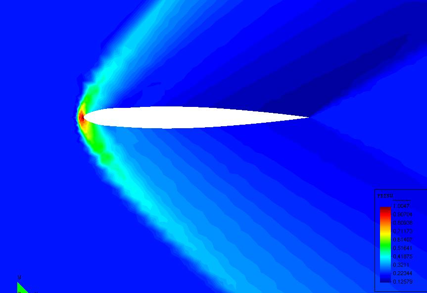
The starting point of the idea is that this kind of shapes exists indeed. That is to say: it is possible to find shapes that while keeping good aerodynamic properties, produce low sonic boom. We will try to find them by optimizing more traditional ones. For instance, take the ONERA M6 wing in Figures 4 and 5. Consider then the airfoil obtained by cutting a section at mid wing-span. This 2D airfoil is to be placed within a supersonic flow, with the same angle and Mach inflow, and the shock wave propagation is calculated with a second order 2D code in an adhoc bidimensional domain. In Figure 2 we compare the flows obtained for both the original and the optimized profiles of Figure 4, right. Figure 3 shows the effect of the optimization, that can be resumed in this:
- The near field pressure peak has clearly diminished. This is attained by making a more acute leading edge with a flattened downards face.
- The pressure peak has been initially distributed in a wider area, by flattening the downwards face and slightly twisting the trailing edge, creating a sort of flap. This will also maintain the lift coefficient.
- The small shock produced by the twisted trailing edge has a very important function: it has helped to quickly focalize the sharp first compression, but whith no over-expansion behind it.
- The last vertical position registered in Figure 3 lies at about 6 chord lenghts below the airfoils, equivalent approximately to a distance of 10 chord lenghts measured from the profiles to the propagated shock. There, while the original profile has developed the typical N-shape pressure distribution, the optimized one has a smaller pressure peak, a smaller pressure impulse (the integral of the pressure over the value at infinite) and no overexpansion following the first peak.
 |
 |
 |
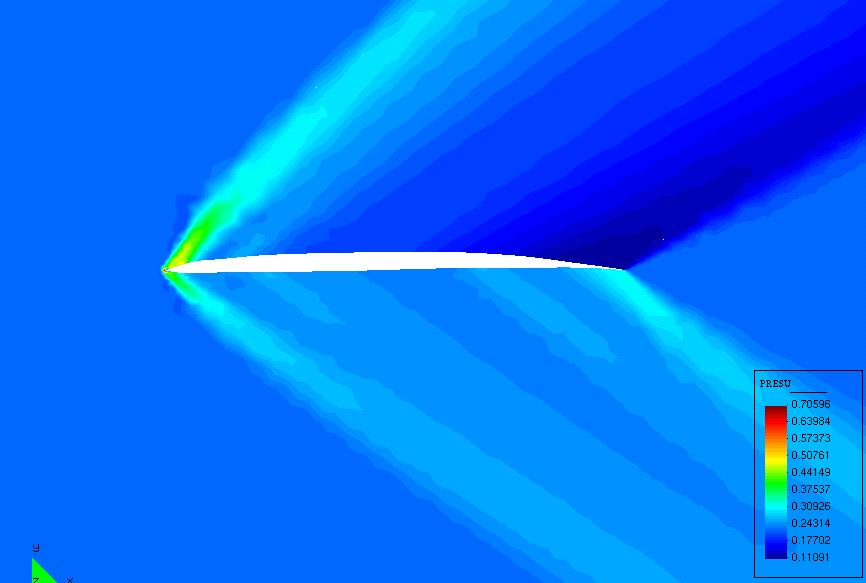 |
Figure 2. Original (right) and optimized 2D sections
from the M6.
Shock wave propagation (top) and pressure contours.
Shock wave propagation (top) and pressure contours.
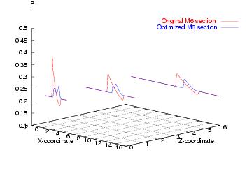
Figure 3. Shock wave propagation at 0.5, 3 and 6 unit length below
the airfoils.
Results:
This is a brief collection of the latest results. For a thorough gallery, refer to the Up-to-date publication's list below, particularly to [a] . This collection includes two sections, rigid shapes optimization and aeroelastic coupled optimization. The first section, which is displayed here, includes three examples. First, an ONERA M6 wing. This example has been used for testing the strategy. This very coarse mesh example is doubly useful: the results are fairly good and the scheme has been proven to be really robust. Then a Generic Aircraft's Nose is optimized in order to see more qualitative results. In this case, there are no constraints on lift. Finally, the target of the project, Dassault's projected Supersonic Bussiness Jet is put to a test. The isolated wings, extracted from the available original geometry, are taken as a starting point case. Finally, the full aircraft is considered. The optimization of the double sweep angle wing has given very interesting and rather surprising results, completely different than those of the M6 wing.
While the first two examples are computed in in situ LINUX based PCs, the size of the SBJ (~1M tetrahedra) make it unbearable for rather small PCs. Therefore, the code was parallelized and used in the shared memory parallel computer SGI Origin 3800 from CINES center in France.
A. Rigid shapes optimization
1. ONERA M6 wing
 |
 |
Figure 4. ONERA M6. Left, skin mesh and surface
pressure distribution.
Right, original (black) and optimized (brown) profiles.
Right, original (black) and optimized (brown) profiles.
Figure 5. ONERA M6. Pressure below the wing.
2. Generic Aircraft's Nose
|
 |
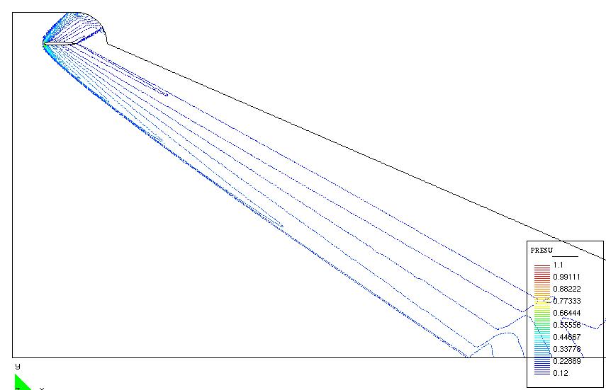
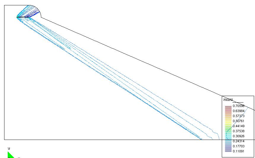
Figure 6. Generic Aircraft's Nose. Left, pressure distribution in a plane
below. Right, original (grid shown) and optimized profiles, vertical mid cut.
|
|
Figure 7. Generic Aircraft's Nose. Pressure distribution for the plane shown
in Figure 6. Left, original. Right, optimized. (For comparison, the color scale is the same
in both figures)
3. Dassault Aviation's Supersonic Bussiness
Jet (SBJ)
|
|
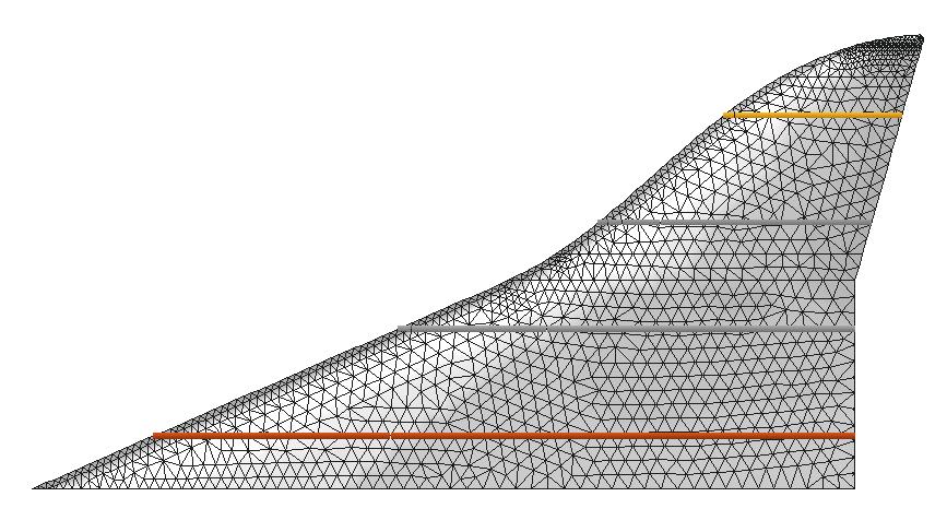
Figure 8. SBJ. Left, original geometry. Right,
extracted, simplified wing showing the four
reference sections A, B, C and D (from outboard to inboard).
reference sections A, B, C and D (from outboard to inboard).
 |
 |
Figure 9. SBJ. Left, Mach number contours. Right,
gradient of the cost functional
for the first optimization iterate and for the full plane.
for the first optimization iterate and for the full plane.
 |
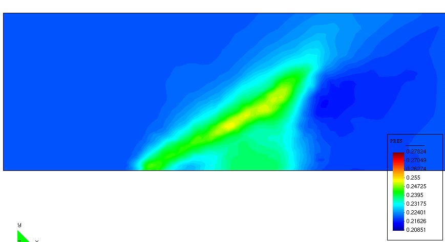 |
Figure 10. SBJ, isolated wing. Pressure distribution
in a plane below the wing.
Left, original wing shape. Right, optimized wing shape. (For comparison, the color scale is the same
in both figures)
Left, original wing shape. Right, optimized wing shape. (For comparison, the color scale is the same
in both figures)
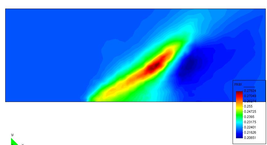
 |
 |
Figure 11. SBJ, full aircraft. Pressure distribution
in a plane below the aircraft.
Left, original wing shape. Right, optimized wing shape. (For comparison, the color scale is the same
in both figures)
Left, original wing shape. Right, optimized wing shape. (For comparison, the color scale is the same
in both figures)
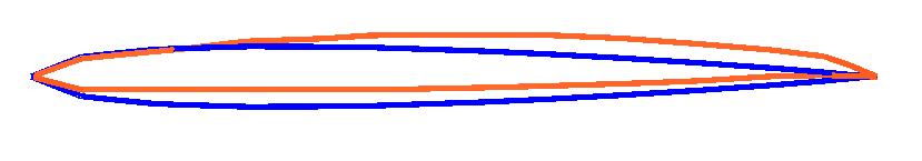 Section A |
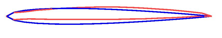 Section B |
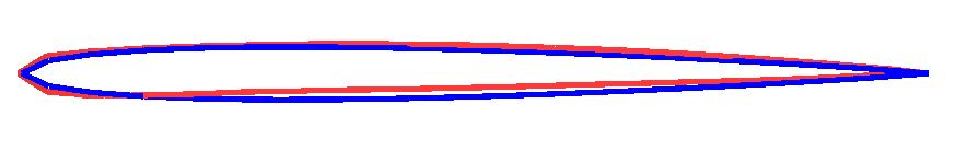 Section C |
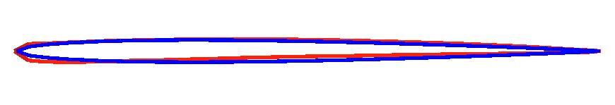 Section D |
Figure 12. SBJ, isolated wings. Original (blue) and optimized (red) profiles at the four sections
shown in Figure 8, right. The original wing volume is preserved.
The authors are very grateful to Dr. Michel Mallet at Dassault Aviation for sharing with us his deep knowledge of aircraft applied research through long discussions. We are grateful also to Prof. Charbel Farhat, to Dassault Aviation for providing the geometries and to CINES for the computing facilities. All results' post-processing has been done using GiD.
Up-to-date publications' list derived from the project:
[a]. M. Vázquez, B. Koobus and A. Dervieux
Aerodynamical and sonic boom optimization of a supersonic aircraft.
INRIA Research Report RR-4520. Download (~1.5M).
[b]. A. Dervieux, B. Koobus, C. Farhat, M. Vázquez, R. Carpentier and E. Schall
Numerical models for computing unsteady fast flows and their interaction with structures.
Presented in the WEHSFF 2002, West East High Speed Flow Field Conference.
Marseille, France. April 2002.
[c]. A. Dervieux, F. Courty, M. Vázquez and B. Koobus
Additive multilevel optimization and its application to sonic boom reduction.
Presented at Numerical Methods for Scientific Computing - JP60 Meeting
Variational Problems and Applications
Jyvaskyla, Finland. June, 2002. Download Preprint (~1M)
[d]. M. Vázquez, B. Koobus and A. Dervieux
Multilevel optimization of a supersonic aircraft.
Submitted to Finite Elements in Analysis and Design. 2002. Download Preprint (~1.2M)
[e]. M. Vázquez, B. Koobus and A. Dervieux
Aeroelastic coupling in sonic boom optimization of a supersonic aircraft.
INRIA Research Report to appear. 2002.
[f]. A. Dervieux, M. Vázquez, B. Koobus and Ch. Farhat
Spatial discretization issues for the energy conservation in compressible flow problems on moving grids.
INRIA Research Report to appear. 2002.
References:
[1]. D.J. Maglieri and K.J. Plotkin
Aeroacoustics of flight vehicles: theory and practice.
Acoustical Society of America Publications. Book edited by H.H. Hubbard. 1991.
[2]. B. Mohammadi and O. Pironneau
Applied shape optimization for fluids.
Clarendon Press - Oxford. 2002.
[3]. N. Marco and A. Dervieux
Multilevel parametrization for aerodynamical optimization of 3D shapes.
Finite Elements in Analysis and Design. 26, pp. 259-277, 1997.
[4]. J. Reuther and A. Jameson
Aerodynamic shape optimization of wing and wing-body configurations using control theory.
AIAA Paper. 95-0123. Aerospace Sciences Meeting and Exhibit. 1995.
[5]. N. Marco, B. Koobus and A. Dervieux
An additive multilevel preconditioning method.
INRIA Research Report. 1994.
Mariano Vázquez is the web page's owner.