Aeroelastic Coupling in Sonic Boom Optimization
of a Supersonic Aircraft
Authors' e-mails: of a Supersonic Aircraft
Mariano.Vazquez@sophia.inria.fr
Alain.Dervieux@sophia.inria.fr
koobus@darboux.math.univ-montp2.fr
This web page is no more than a brief summary of the project. For the complete sources, please refer to the "Up-to-date publication's list" section and download the papers available, here.
This research is part of the project:
under way in INRIA - Sophia Antipolis, France.
Research sketch:
A three module scheme
The coupled aerodynamic-aeroelastic optimization problem is then divided in two phases, that repeat iteratively until a convergence criteria is achieved. To a first aeroelastic analysis phase it follows an aerodynamic optimization stage. Each phase corresponds to a different module, and a there is a third module connecting them, a remeshing tool, due to the fact that the optimizer modifies only the surface discretization, and so a corrected volume mesh is needed as a link between the optimization and analysis modules.
The aeroelastic analysis module: a loosely coupled fluid-structure solver.
The aerodynamic optimization module: an aerodynamic optimizer.
The remeshing module: a remeshing tool.
The aeroelastic analysis module
The solution of the coupled fluid-structure problem is computed by a staggered solution procedure in time. This kernel yields a coupled fluid-structure static analysis using a pseudo time advancing scheme with two stages: a fluid evaluation stage followed by a structural computation, based in the pressure distribution given by the preceding one. At the first, fluid stage, a mesh conforming to the structure deformation is built by moving the vertices with a pseudo-structural model. Then the flow is advanced towards steadiness on this mesh. The spatial discretization of the compressible flow Euler equations is based on a finite volume method, using a second order space accurate scheme based on Roe solver. For addressing the problem of flow simulations on moving grids, an Arbitrary Lagrangian Eulerian formulation is incorporated in the flow solver (in the present case of static coupling, this is not essential when the mesh is moving from the initial position to the new one). Next, at the structural stage, the pressure loads are applied to the structure and the resulting displacements are computed. The structure is represented by a finite element model on a thin plate, embedded in the wing, which is a simplified model of the internal structure. The displacements are finally transferred to the wet surface wing, producing a deformed volume mesh. This volume mesh is the output of the aeroelastic analysis module.
References:
C. FARHAT and M. LESOINNE,
On the accuracy, Stability and Performance of the Solution of Three-Dimensional Non-Linear Transient Aeroelastic Problems by Partitioned Procedures. AIAA paper 96-1388. 1996.
C. FARHAT and M. LESOINNE and N. MAMAN,
Mixed explicit/implicit time integration of coupled aeroelastic problems: three-field formulation, geometric conservation and distributed solution. Int. J. Num. Meth. Fluids. 21, pp. 807-835. 1995.
The aerodynamic optimization module
The aerodynamic optimizer is an evolution of that of the first stage of the project. It is a CAD-Free based algorithm: the design parameters space is set by the physical positions of each of the skin discretization nodes placed in the shape to be optimized. Here, the shapes derived from the the iterative optimization process are characterized using a transpired perturbation. According to this, to each of the skin nodes it is assigned a scalar which corresponds to a (small) displacement in its normal direction. High frequency effects in space are dramatically reduced by using a multilevel preconditioner applied to the shape gradient. In order to cope with the probably very large number of parameters defining the target shape, a discrete adjoint problem is solved. The optimization algorithm is designed to reduce the sonic boom downards emission keeping some target aircraft performance properties, basically lift and/or drag. The incidence angle is corrected at each iteration to recover the lift that the shape modifications could not improve, given a target lift.
References:
Check the project's web page, here.
The remeshing module
The remeshing module works as an interface between the aeroelastic module and the optimization one. The aeroelastic module already includes a remeshing algorithm to take into account the shape deformations. They are transferred to the optimization module as a modified volume grid, called thecruise mesh for a given coupling iteration, suitable to be the optimizer input. On the other hand, the optimizer's output is a shape correctiondefined on the surface nodes according to the transpiration condition. Through a remeshing algorithm that adapt the mesh to the new, optimized surface, a corrected volume grid is produced. This volume grid will be used in turn as input by the aeroelastic module. The algorithm generates a new mesh by moving the nodes of the input one with a pseudo-structural model, under the constraint that the new boundary nodes are the result of the movement on input ones with the input shape correction.
Results:
This is a brief collection of the latest results. For a thorough gallery, refer to the Up-to-date project's publication's list. The wings of the Dassault Aviation projected Supersonic Bussiness Jet (SBJ) are optimized according to the proposed scheme. The isolated wings, extracted from the available original geometry, are taken as a starting point case.
 |
 |
Figure 1. SBJ wings. Left, wing discretization showing location of three cross-sectional cuts. Right,
plate used to model the aeroelastic behaviour.
 |
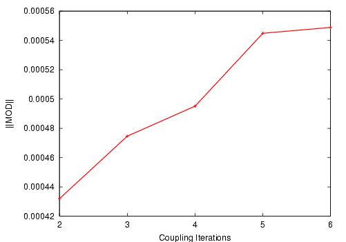 |
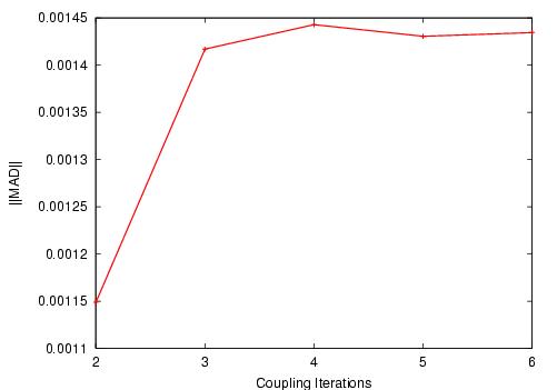
Figure 2. SBJ wings. Coupled scheme convergence through the coupling iterations.
Left, Per-surface-node (called "Mean") Aeroelastic Displacements.
Right, Mean Optimization Deformation.
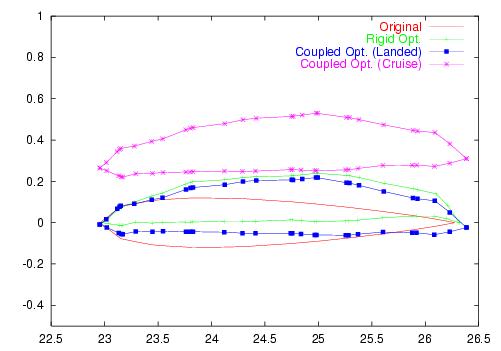 Outboard airfoil |
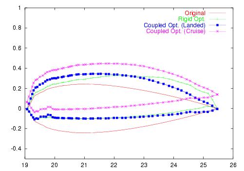 Middle airfoil |
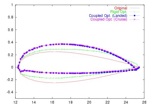 Inboard airfoil |
Figure 3. SBJ wings. Comparison of the optimized landed coupled and rigid airfoils at the three locations. Also the cruise coupled optimized airfoils are shown. |
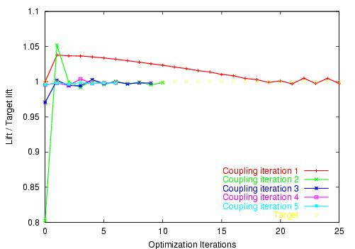 Lift coefficient |
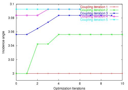 Incidence angle |
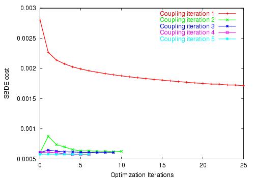 Sonic boom term in the cost functional |
Figure 3. SBJ wings. Evolution
of different parameters for each of the coupling iterations. |
Mariano Vázquez is the web page's owner.