

Laurent Blanchet
Due to mankind exploitation of space, many thousands of man-made objects are now in space. As we know, space is pretty much empty. However, due to mankind needs, this is not the case in the vicinity of Earth. The situation degrades rapidly in Geostationary Earth Orbit (GEO) and worsen as we go toward Low Earth Orbit (LEO): there is still a lot of space, but for a first part the useful orbits are kind of the same, and there is a lot of objects due to the commercial use of those orbits (see figure 1).
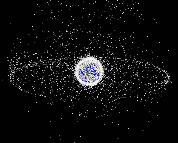
Fig. 1: Objects tracked by NASA (95% are debris) (only >10cm are tracked). source NASA, Orbital Debris Program Office
One criterion has been worked out by ESA [Hyde, 2010] to determine which debris should be retrieved first: the mass times the probability of impact of an object (highly related to the size of the debris). This criteria makes rockets' third stages priority targets. (The third stage of a rocket is a mini-rocket that puts the satellite at the right place at the right speeds. See figure 2.)
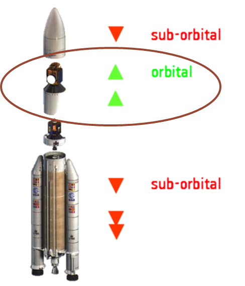
Fig. 2: Decompostion of a rocket by post-deployment situation (credits ESA).
The Swiss Space Center is putting together an Orbital Debris Removal (ODR) mission called Clean-mE.
In a previous thesis, in the framework of this project I determined a scenario for a robotic ODR mission. However the reaction of the base to the actions of the robotic components of the satellite (see figure 3) induces rotation around the center of rotation of the robotic satellite, whose position depends on robot's current configuration.

Fig. 3: Space robots' base reacts: each action induces a rotation around the instantaneous mass center. (Credits Yoshida)
To handle this, I also implemented a dynamic control using Yoshida's Generalized Jacobian [Yoshida, 2003].
This project concerns the design of hardware allowing to dock a manipulator in a reaction-free fashion. This reaction-free test-bed has two purposes: first test the algorithm of the previous thesis with an actual serial manipulator and second, to emulate contact dynamics in the grabbing phase of the proposed scenario.
Fig. 4: Schematic of the three platforms, along with the mock-up chaser.
As depicted on figure 4, the design problem is decomposed in 3 separate problems:
The goal is to put a KUKA's LWR in the chaser mock-up, but a small sized manipulator would be used first to compare models and physical prototype. In this project, I designed two AP and one PP with geometric, kinematic and dynamic considerations for those two cases. The AP and PP (a Delta robot) for LWR case are at a conceptual state. The small-sized AP is at machining phase and use a twin manipulator to keep the centers coincident (no need for PP). The CAD model of two AP are depicted figures 5 & 6.
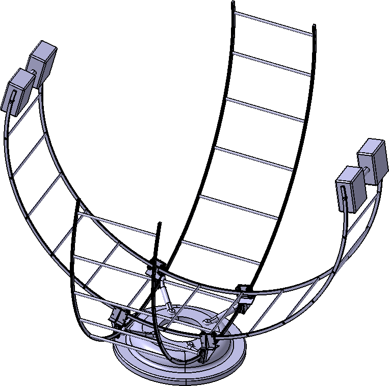
Fig. 5: LWR-sized AP, without gliders counterweigths for clarity.
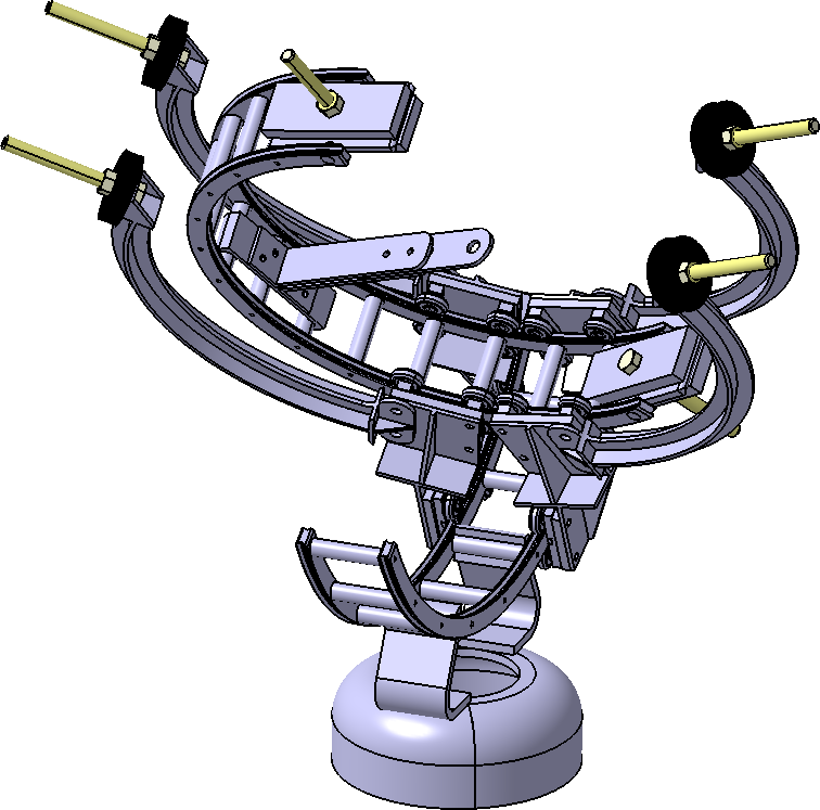
Fig. 6: DoFBox (1dof module developped at LASA/EPFL) sized AP.
Due to mankind exploitation of space, many thousands of man-made objects are now in space. As we know, space is pretty much empty. However, due to mankind needs, this is not the case in the vicinity of Earth. The situation degrades rapidly in Geostationary Earth Orbit (GEO) and worsen as we go toward Low Earth Orbit (LEO): there is still a lot of space, but for a first part the useful orbits are kind of the same, and there is a lot of objects due to the commercial use of those orbits (see figure 1).
Fig. 1: Objects tracked by NASA (95% are debris) (only >10cm are tracked). source NASA, Orbital Debris Program Office
One criterion has been worked out by ESA [Hyde, 2010] to determine which debris should be retrieved first: the mass times the probability of impact of an object (highly related to the size of the debris). This criteria makes rockets' third stages priority targets. (The third stage of a rocket is a mini-rocket that puts the satellite at the right place at the right speeds. See figure 2.)
Fig. 2: Decompostion of a rocket by post-deployment situation (credits ESA).
The Swiss Space Center is putting together an Orbital Debris Removal (ODR) mission called Clean-mE.
In the framework of this project I determine in this thesis a scenario for a robotic ODR mission. However the reaction of the base to the actions of the robotic components of the satellite (see figure 3) induces rotation around the instantaneous center of rotation of the robotic satellite.
Fig. 3: Space robots' base reacts: each action induces rotation around mass center (whose position depends on robot's instantaneous configuration). (Credits Yoshida)
There are two ways if dealing with the reaction of the base problem. The first one is: we have algorithms working for a fixed base, when its reaction is absorbed by the Earth: let's mimic this behavior by putting components (reaction wheels) on the base to keep a fixed attitude. The second approach is to modify the algorithm to acknowledge the reaction of the base.
One well-known algorithm to control serial manipulator is using the jacobian matrix to determine local minima for the articular functions for the task coordinates.
Yoshida derived a matrix called Generalized Jacobian Matrix [Yoshida, 2003] acknowledging the motions of the base (see fig. 4). In front of the comparative results using this algorithm or ground-based jacobian with compensated attitude [Yoshida, 2003], I implemented a dynamic control using Yoshida's Generalized Jacobian using an acceleration scheme (see fig. 5) in RobotToolKit simulator (made by Eric Sauser). See fig. 6 for an example of the CAD model of the devised robotic space chaser in RTK simulator, following a BSpline trajectory (the trajectory is depicted as evenly-time-spaced little blue balls, with the control polygon in a thin red line).
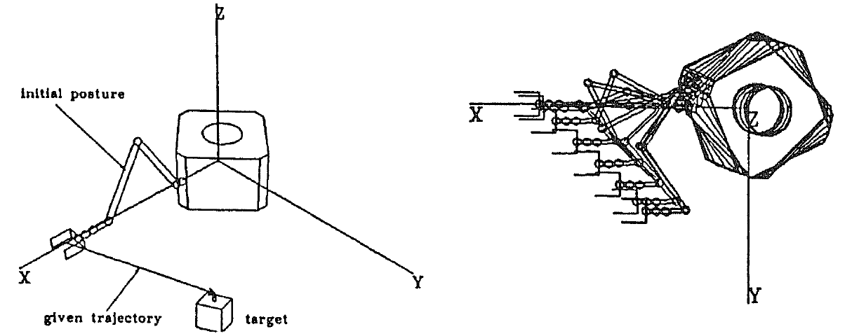
Fig. 4: Simulation picturing a robotic satellite: on the left, the initial situation, with the task; on the right, the motion (one frame per second). (Credits Yoshida)
Fig. 5: Control algorithm used (Resolved Acceleration control).
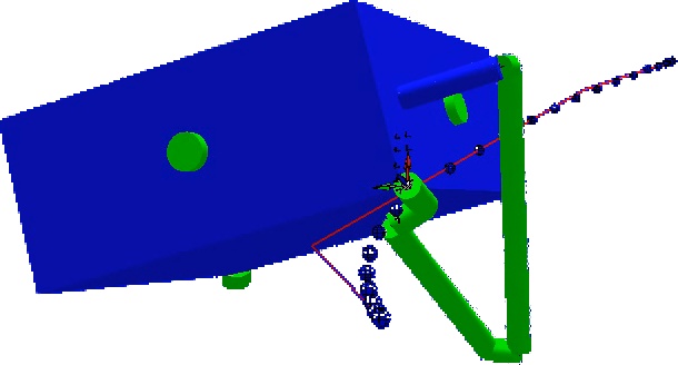
Fig. 6: CAD model of the chaser in RTK simulator using GJM algorithm to follow the trajectory (little blue balls, depicting a BSpline trajectory, while the red line is the control polygon). (Credits RTK: E. Sauser)
In humanoid robotics, the problem of interaction (especially with humans) is still yet to be tackled. In the Joint Robot Laboratory, a joint team between CNRS (France, nation-wide research organization) and AIST (Japan, counterpart of CNRS), algorithms for human-robot tasks are being developed.
In order to prevent harming people and also giving the humanoid robots the ability to touch, I did a study about conceptual design for an haptic (sensible) suit.
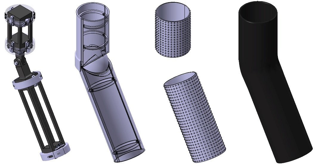
Fig. 1: Exploded view of the whole design for an arm, from left to right: the idealized beam-like robot links (dark) and the distributed pressure sensors (gray rings), the bumper, the contact location tactile binary switches, the compliant cover.
My haptic suit is divided in 4 specialized parts from the robot's parts to the exterior of the robot (from left to right on figure 1): instrumented links (gray rings) to the robot's parts (black beams), a shell to deflects the actions on the suit to the sensors (in the rings), an array of binary switches to determine the location of the contact, and a compliant skin to fill in the gaps between the switches. As constraints, the suit must left the possibility to be entirely taken apart; it also must be as less invasive as possible towards the robot's links, and must not interfere with cable and electronics generally in the middle of the parts. To keep the bulk low, the link with the robot's parts are made out of the sensors (see figure 2 for the set up of the sensor dedicated to the measure of the force along the axis of the robot's part as an example of the linking). This set-up allows to measure any force applied on the suit's robot part, as demonstrated by the screw of the measured forces according to the parameters on figure 3:
| Tsensors(P) = |
|
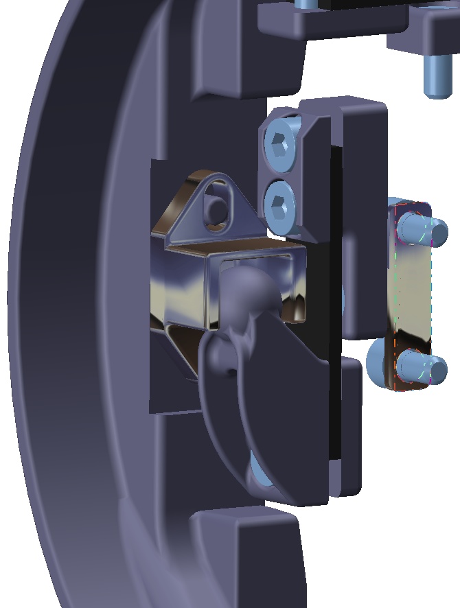
Fig. 2: CAD model of the arm's suit, with focus on the set-up of the sensor for along-the-arm forces.
Fig. 3: Schematic with parameters of the instrumented suit.
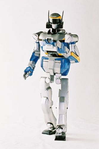
Fig. 1: The HRP2 robot.
HRP2 is a 58kg, 1.54m tall humanoid robot, able to walk and grab things. However when it walks and hold things at the same time, there is a lot of vibrations and shocks coming from the pace.
Anthony David, while studying an external passive shock-absorbing mechanism (here), determined Young modulus and Poisson's ratio for soles for HRP2. Using this data, I determined a list of suitable materials, and among them, I chose one based on cost of the raw material and process costs.
A second part of my study was to determine the wrap of either a compliant sole (model fig. 2a) or a compliant join (model fig. 2b) when subject to dynamic, kinematic and kinetic effects.
| Fig. 2a | Fig. 2b |
Fig. 2: Schematic of the model used for the determination of the wrap of the compliant part on the sole (2a) or in the join (2b).
I solved this by using continuum mechanics, thus obtaining only a closed form for the displacement field of the compliant parts. However those forms are still ideal for Finite Elements Analysis, and allow to conclude that compliant articulation generates perturbations on the entire join, thus on the leg, whereas the sole limits the perturbations to a local field.
In addition to the compliant part, the motion of the feet while performing one step is also very important. As we separate the two problematics, we need a step generator algorithm to describe the motion of the feet, but with the speeds at the interruption or re-establishement of the contact sole-ground as inputs (later designated as initial and final speeds).
I created such an algorithm for the control of the motion of the foot handling the three positions using B-splines and the three orientations using slerps. The constraints are smoothness of the motion, which is interpreted as continuous acceleration curves, initial and final positions and speeds, and also the height of an hypothetical obstacle to step over (see figure 3).
On the figure are depicted in bluish the foot, in green the vectors of initial speed (on the left), final speed (on the right), the obstacle as the black cube and the desired trajectory as the black curve.
Fig. 3: Parameters for the step generator.
Fig. 4: The HRP2 robot.
The result is shown in the video figure 4, with the small red balls evenly time-spaced to show the evolution of the speed. The complex computation of the wrap of the compliant sole was not in this simulation, thus the initial and final speeds are nil. The foot prints (placement of the feet for a given trajectory) are computed by a pattern generator (cf Olivier Stasse), while the motion of the feet in-between the foot prints is the result of my step generator. If the video does not work (maybe the case with IE) use those two links directly to the files: webm (552Ko) and mp4 (3.6Mo). The video figure 4 is a small quality, web-optimized webm file. The original mpg videos are available here and here (20.8Mo and 13.1Mo).
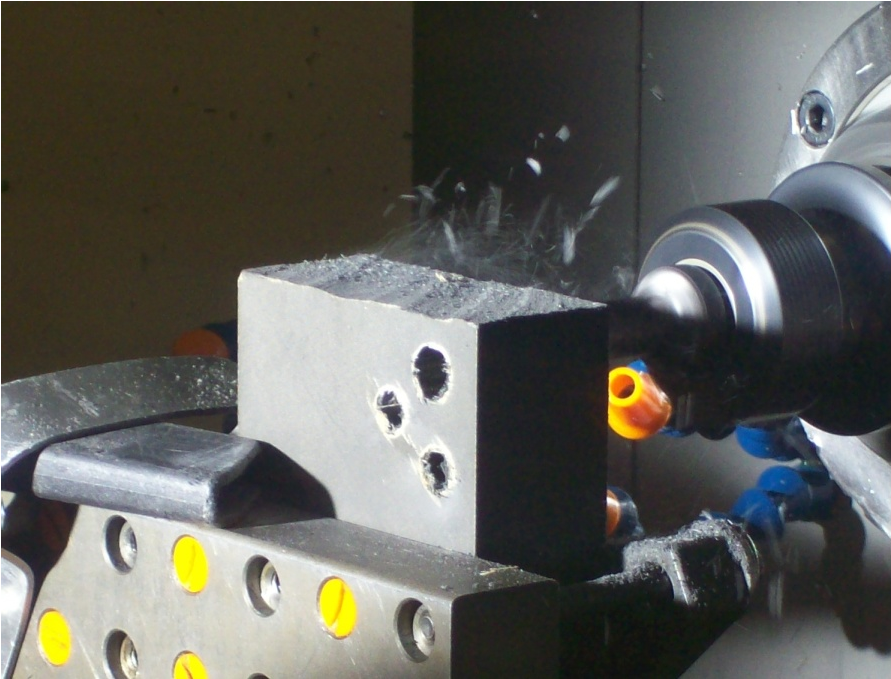
Fig. 1: Experimental set-up and machining studied.
Contrary to metallic materials, there is not much data on composite material machining. In a metallic material case, the material is homogeneous and enough data on material's machining as been compiled to extrapolate the machining parameters of any variation to get a good enough machining. When it comes to composite materials, there not only is not much data but also the behavior can be radically different from one to the other or to a metallic material's.
In this work, we tried to determine through a drilling operation if high-speed or infra-red cameras could be used to assess the influence of machining parameters (tool and forward velocity) on the machining's quality of a composite material.
On figure 1 is depicted the mechanical set-up of the composite sample during the drilling operation.
The results obtained are as depicted on figure 2. The fast camera is useful only in a binary sense as it allows to determine is the machining's parameters were correct or not (see in particular the case of carbide-bit drill compared to other tools). The IR camera, given a thermal law of the material (which not straight-forward in composite materials cases) gives continuous sets of data that can be used to extrapolate the parameters of the machining.
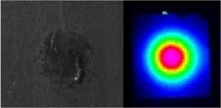
Fig. 2: Examples of results obtained with the fast camera (left) and the IR camera (right).
 , licensed under a Creative Commons Attribution-NonCommercial-NoDerivs 3.0 France License by INRIA and/or Laurent Blanchet |
Designed by Free CSS Templates & LB |
Validate
XHTML
, licensed under a Creative Commons Attribution-NonCommercial-NoDerivs 3.0 France License by INRIA and/or Laurent Blanchet |
Designed by Free CSS Templates & LB |
Validate
XHTML
