Texture Assignment
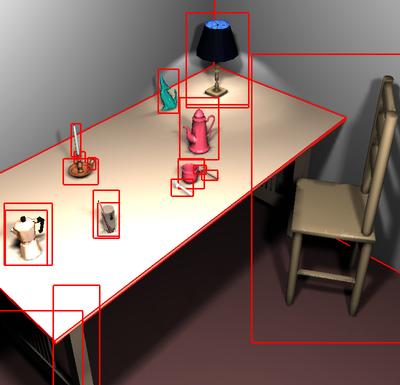
During rendering, to each object a texture is applied that contains the corrections for this particular object from the current view. However, we do not assign a texture to each scene triangle, but to entire groups that form an object, e.g. a cup, a chair, or a book. For this purpose a scene hierarchy is needed. The hierarchy level to which the textures are assigned depends on the screen size of the object and on its depth range within the current view. The image below shows the frames assigned in an example scene.
Since mapping a texture to composited objects is difficult
in general, we project the corrective textures onto objects by point projection
from the current view point. By this, ambiguities between ray samples and
texture pixels are avoided. However, the mapping is spatially not fix with
a changing view point. The resulting artifacts depend on the depth range
of the object with respect to the current camera, which is kept small by
the criterion described above.
Texture Generation
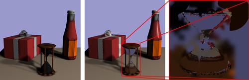
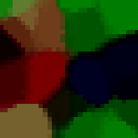
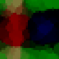
Samples are splatted into the textures using a Voronoi diagram creation method. Blending is used to blur the Voronoi cell boundaries. Textures are reused from frame to frame, so the splatting has only to be done once per ray tracing sampling. According to the camera movement the splatted samples age and loose validity, such that old and thus uncertain samples are likely to be overwritten by new ones. The image below shows how a texture (right) is reconstructed by splatting 20 and 100 random samples (left and center, respectively).
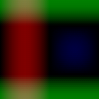
We store the average size of recent samples for each texture. If this size becomes large, the splatting procedure is time intensive, and the resolution of the texture is probably too big. On the other hand, a small splatting size indicates that the texture is too coarse to hold the information of all samples. We therefore adapt the texture resolution on the fly according to this average splat size.
Sample Generation
Ray samples are concentrated to regions that exhibit the largest error. We achieve this with a priority queue of sample requests. For each new view, the queue is initialized with uniformly distributed positions and with a number of sample positions that exhibited the largest errors in previous views (significant samples). This queue is processed ideally on parallel or remote processors. When a sample exhibits a large correction value, a number of new child samples in the surrounding region is inserted into the queue with a priority value that reflects the detected error.
Implementation
We implemented the corrective texturing approach using the rendering of a finite element global illumination solution as fast, interactive hardware pass and a standard distribution ray tracer as slow high quality sample generator. The ray tracing samples are acquired on a remote multiprocessor machine, the display is generated on a high-end graphics workstation.
Results
We could achieve frame rates of about 5 frames per second for scenes of moderate complexity (50.000 finite element patches). In this time about 4000 samples can be obtained per frame. The overhead for the generation of textures and the hardware generation of views is about 100%, i.e. a fully parallelized ray tracer could generate the final solution in half the time we need in our system, but with the corrective textures continously intermediate approximate views are generated in fractions of seconds, and the camera can be moved any time.
Even for a rather complex test scene with 600.000 radiosity patches we achieve display rates of 1-2 frames per second. In this case, the hardware rendering pass becomes a restricting factor, especially since due to hardware restrictions with respect to additive texuturing we have to render in two or three passes. With more recent graphics boards this restriction is lifted, so a significant speedup can be expected.
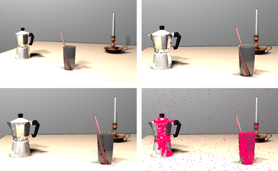
The image below shows one of our test scenes, rendered interactively with corrective texturing. The upper left image is a well converged view. In the upper right, the camera was moved to the right, but the textures are not modified. For the lower left image, 10.000 ray tracing samples were used to adapt the textures, the sample positions are shown in the lower right.
see also: M. Stamminger, J. Haber, H. Schirmacher, H.-P. Seidel, Walkthroughs
with Corrective Texturing, Rendering Techniques 2000 (Proc. Eurographics
Workshop on Rendering), Springer, 2000