1. Installing Odin on a new Process
Installing Odin on a new process goes as follows:
- Build Odin on each machine that will be used by the process
for data acquisition, control, and monitoring purposes.
- Configure the part of Odin that runs on each machine (Bioprocess,
Supervisor or User Interface).
- Write or adapt startup scripts, shutdown scripts and IOR servers.
1.1 Building Odin
If your are using Ubuntu we recommand using the ‘install-Ubuntu.sh’
script that make all the job for you, just let it guid you through the different steps.
This install process require an internet connection.
Building Odin is done by following the instructions available in
the README file in the top directory. The README file also contains
troubleshooting instructions.
Under UNIX systems, it is generally as simple as installing dependencies,
and then executing
./configure
make
Alternatively, a ‘make_odin.sh’ file is provided that builds odin,
setting up the appropriate environment variables.
To use it, simply execute
./make_odin.sh
Dependencies names are provided for Ubuntu distributions.
Here is a list suitable for Ubuntu 8.04 to Ubuntu 10.04 :
- build-essential
- gfortran
- python-dev
- qt4-dev, libqt4-dev, qt4-dev-tools
- omniidl4, omniorb4, libomniorb4-dev
- pvm-dev
- libx11-dev, libxt-dev
- libssl-dev
- libxext-dev
- libboost-dev
- libxml2-dev
- gettext
- libblas-dev
- liblapack-dev
- libpcre3-dev
- libxmu-dev
A few precisions about these dependencies:
- build-essential is a set of packages needed to compile some code on ubuntu.
- gfortran, pvm-dev, libx11-dev, libxt-dev, libxext-dev, libxml2-dev, gettext,
libblas-dev, liblapack-dev, libpcre3-dev, libxmu-dev are needed by Scilab.
- qt4-dev, libqt4-dev, qt4-dev-tools are needed by the User Interface.
- omniidl4, omniorb4, libomniorb4-dev supply the OmniORB library and
IDL compiler (OmniORB is a CORBA broker). This library allows different parts
of the application to be run on different machines connected over a network.
- python-dev, libssl-dev are needed by OmniORB (CORBA support).
- libboost-dev is needed for a few instances of boost::shared_ptr,
but we aim to get rid of this dependency.
Under Ubuntu, the dependency library-name can be installed
by executing
sudo apt-get install library-name.
For instance, installing libraries libboost-dev and
libssl-dev can be done by executing
sudo apt-get install libboost-dev libssl-dev
A note about libmodbus:
The TES and Alto processes (code that acquires data and sends orders to/from
TES and Alto modules supplied by Leroy Automation) requires that libmodbus
be installed on your machine. This library is usually not supplied as a
package by common Linux distributions, so it must be installed from source.
An archive (‘libmodbus-2.0.0.tar.gz’) is provided in the ‘contrib’
directory. Extract it to a place of your choosing, then run
./configure
make
sudo make install
C++ compiler
Odin has been built and tested with the g++ compiler.
Under Ubuntu, the packet build-essential provides g++.
Install it by running sudo apt-get install build-essential.
1.2 Setting up the Bioprocess
This chapter describes the Bioprocess setup.
Connecting Odin to a physical process entails choosing the appropriate
hardware drivers, configuring those drivers and making sure that
the Bioprocess is accessible to the outside world.
1.2.1 Hardware drivers
Hardware 'drivers', such as TES boards drivers, MccDaq boards drivers,
and the Simulator acquire data from the "real world" and carry orders.
To an Odin installation, a set of inputs (Sensors) and outputs (Actuators)
that use the same driver is known as a "Bioprocess".
Bioprocess configuration is defined by the driver implementer.
To install Odin on a bioprocess, you should take note of all relevant
aspects of your setup (serial ports names, IP addresses, sensor
and actuator names and location on the acquisition boards...).
1.2.2 Bioprocess Configuration
Configuring a Bioprocess mostly means mapping names (a 'name' is
an UID in Odin parlance) to inputs/outputs on an acquisition board,
or a simulator, and setting up communication details (name of a serial port,
IP address of an Alto module) and choosing the data acquisition period if
applicable.
Each Bioprocess implementor is free to choose its configuration
file format (altough some factoring should be envisaged), and in some cases
(e.g. the Simulator) we dispense with a configuration file (the Simulator
configuration is described directly in the Scilab code).
1.2.2.1 Example: the TES process
TES boards are data I/O modules that are connected over a Modbus network.
These boards provide digital and analog inputs and outputs. To set up a TES
module with Odin, you should:
- Create (or modify) the configuration file ‘tes-settings.xml’.
- Run the ‘tesProcess’ executable.
Let's cover the ‘tes-settings.xml’ file in more detail:
look at the example file, and then read below for explanations.
<!DOCTYPE tes-settings>
<tes-settings>
<version>1</version>
<serial-device>/dev/ttyS1</serial-device>
<sample-interval>30</sample-interval>
<sensor>
<type>Gen1w</type>
<slave>2</slave>
<!-- third analog input --> <!-- addresses are written in base 10 -->
<address>6</address>
<device-uid>ext-tempIn</device-uid>
<group>ext</group>
<unit>C</unit>
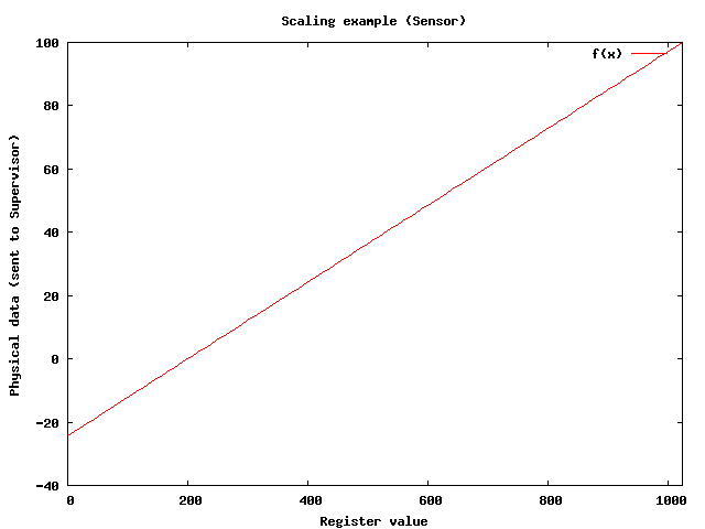
<!-- in this example, a raw value of 200 is a temperature of 0 degrees Celsius, and a raw value of 1023 is a temperature of 100 degrees Celsius -->
<scaling>
<xmin>200.0</xmin><ymin>0.0</ymin>
<xmax>1023.0</xmax><ymax>100.0</ymax>
</scaling>
<domain>
<min>-10.0</min>
<max>65.0</max>
</domain>
<validityPeriod>3600</validityPeriod>
</sensor>
<sensor>
<type>OnOff</type>
<slave>2</slave>
<lane>1</lane>
<device-uid>ext-pumpStatus</device-uid>
<group>ext</group>
</sensor>
<sensor>
<type>Gen2w</type>
<slave>1</slave>
<!-- input 0 time counter --> <!-- addresses are written in base 10 -->
<base-address>1071</base-address>
<device-uid>ext-pumpTime</device-uid>
<group>ext</group>
<unit>s</unit>
<scaling>
<xmin>200.0</xmin><ymin>0.0</ymin>
<xmax>1023.0</xmax><ymax>102.3</ymax>
</scaling>
<validityPeriod>3600</validityPeriod> <!-- one hour -->
</sensor>
<actuator>
<type>OnOff</type>
<slave>1</slave>
<lane>2</lane>
<device-uid>in-pumpCommand</device-uid>
<group>in</group>
<unit>None</unit>
</actuator>
<actuator>
<type>Gen1w</type>
<slave>1</slave>
<address>25</address> <!-- fifth analog output -->
<device-uid>in-heatCommand</device-uid>
<group>in</group>
<unit>None</unit>
<scaling>
<xmin>0.0</xmin><ymin>0.0</ymin>
<xmax>1023.0</xmax><ymax>1023.0</ymax>
</scaling>
</actuator>
</tes-settings>
version is a version number for future compatibility needs.
It is currently always set to 1.
serial-device is the full name (incl. path) of the serial device
that you want to use to communicate with the TES modules, e.g.
/dev/ttyS1 or /dev/ttyUSB0.
sample-interval is the period of the polling loop, ie the sensors
will be polled every sample-interval seconds.
sensor describes a Sensor (unsurprisingly).
The common attributes for Sensors are:
-
type - describes the type of the data that will be read - one
of Gen1w, Gen2w or OnOff.
-
slave - the Modbus slave number (1-based, 0 means broadcast and
is explicitly disallowed).
-
device-uid - the Unique Identifier that will be used to refer
to this Sensor within Odin. For instance, you will use it to get the latest
data point within Odin Observers and Controllers, or to request historical
data from the Supervisor, or to plot the values of this Sensor over time
within the User Interface.
-
group - name of the group the sensor belongs to.
Gen1w (Generic One Word) and Gen2w (Generic Two Words) Sensors
In addition to the common Sensor attributes,
Gen1w and Gen2w sensors also have the following attributes:
OnOff Sensors
In addition to the common Sensor attributes, OnOff sensors also have
the following atributes:
-
lane - 0-based index of the digital input to be read.
OnOff sensors will always return 0 or 1. Scaling is not available.
The domain attribute is (obviously) not relevant, and does not exist
for OnOff sensors.
actuator describes an Actuator.
The common attributes for Actuators are:
-
type - Type of the data that will be written - one
of Gen1w or OnOff.
-
slave - Modbus slave number (1-based, 0 means broadcast and
is explicitly disallowed).
-
device-uid - a Unique Identifier that will be used to refer
to this Actuator within Odin. For instance, you will use it to request
historical data from the Supervisor, or to plot the values of this
Actuator over time within the User Interface.
Gen1w Actuators
In addition to the common Actuator attribues, Gen1w actuators
also have the following attributes:
-
address - Address of the register to be written to, in base 10.
-
unit - Unit of the order (e.g. celsius degrees,
liters per hour)...
-
scaling - an afine transform that converts the Actuator order
(normally a physical data) to a Modbus register value.
For instance, if we have:
    <scaling>
      <xmin>30.0</xmin><ymin>0.0</ymin>
      <xmax>100.0</xmax><ymax>900.0</ymax>
    </scaling>
then the conversion will go like this (register values are integers
between 0 and 1023):
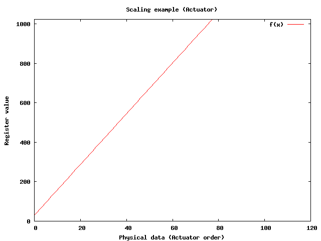
The resulting floating point number will be rounded to the closest integer
(since register values are integers).
Note that while the Sensor scaling converts a Modbus sample value
(proportional to a current or voltage) to a physical value, the Actuator scaling
converts a physical value (e.g. effluent flow rate in liters per second)
to a Modbus sample value (proportional to a current or voltage)
OnOff Actuators
In addition to the common Acutator attributes, OnOff actuators
also have the following attributes:
-
lane - 0-based index of the digital output to be written to.
1.2.2.2 Example: the Alto process
Alto modules are very close to TES boards, but they communicate over
Modbus/TCP (i.e. over an IP network). These modules are also configurable over
HTTP. To set up an Alto module with Odin, you should:
- Create (or modify) the configuration file ‘alto-settings.xml’.
- Run the ‘altoProcess’ executable.
The ‘alto-settings.xml’ is very similar to the file
‘tes-settings.xml’, so we will just mention the important differences:
- The serial port name is replaced by an host name or IP address
(e.g.
<host>10.0.0.100</host>)
- the 'slave' in classical Modbus vocabulary is replaced by a
'Unit Identifier' (noted as 'ui' in the configuration file). It is zero-based
(whereas in classical Modbus a zero slave means 'broadcast' and is not to be
used within Odin). I'm not sure whether the UI has a lot of
practical utility when using Alto modules because these modules normally
have distinct IP addresses, which is enough to identify them.
Leave it to zero if you are unsure.
Please refer to the example file located in ‘bioprocess/altoProcess’.
1.2.2.3 Note about Alto and Tes Processes
Since the hardware support for both these module types is provided by
libmodbus and there is a lot of commonality between them, it would
be a good idea to merge them (and generalize TesProcess and AltoProcess
into a “ModbusProcess” module). It would remove duplicated code and
be more generic (“OnOff” sensors/actuators should be replaced by
“One bit” (masked) sensors and actuators).
1.2.2.4 Example: the Simulator process
The Simulator process is, as the name implies, a virtual process.
Its sensor values are computed by a Scilab script that is
called regularly, passing it the Actuator orders that were computed by
active Controllers.
Using the Simulator process is straightforward: simply place an appropriate
Scilab script in the ‘simulator’ directory and run the ‘simProcess’
executable, passing it the name of the Scilab script without the extension
(e.g. if the file is called ‘sim.sce’, you should run
./simProcess sim).
A simulator example exists at ‘simulator/sim.sce’. It simulates an
anaerobic digestion process using the model AMH1.
Other simulated systems implementations exist in the same directory,
but at this time (2008-OCT-06), ‘sim.sce’ is the only one that
has been validated. Of course, validating other simulators is a
useful activity.
1.2.3 Making the Bioprocess accessible to the Supervisor
If the Supervisor and the Bioprocess are colocated on the same machine, no
particular action is needed (see the startup script configuration for
more information).
If the Supervisor and the Bioprocess are on different machines, they
must be somehow able to exchange messages. OmniORB (the CORBA library
used by Odin) provides a transport layer over TCP/IP networks, so you
are advised to connect both machines to such a network.
Assuming you are using the former, please see "Setting up IOR servers" which
describes a convenient way to expose a CORBA reference
(each reference being served on a distinct port by the host machine).
You may opt to design your own IOR exchange mechanism (using e-mail,
a shared space, another RPC system...) but this is more involved.
1.3 Configuring the Supervisor
The Supervisor is configured by setting options in the file
‘supervisor.cfg’.
This files comprises the following parameters:
speedFactor
sleepTimeMs
Set speedFactor to 1 unless Simulator is used
(in which case it should be
set to the same value as the corresponding Simulator parameter).
sleepTimeMs is the main loop sleep time, i.e. approximate Observer and
Controller computation period (typically a few seconds to a few minutes),
expressed in milliseconds. It cannot be less than 1000 milliseconds
(one second).
The user then places the appropriate Observer and Controller files in the
corresponding directories to have them run by the Supervisor. These files
are executed as follows:
- Observers in filename lexicographical order
- Controllers in filename lexicographical order
For instance, if the directory structure of your installation
looks like this:
+-odin/
  |
  +-controllers/
  | |
  | +-01_ctr_dcoqm.sce
  | |
  | +-02_ctr_another.sce
  |
  +-observers/
    |
    +-obs_xc.sce
    |
    +-obs_z.sce
The order of execution during a control loop will be:
- ‘obs_xc.sce’
- ‘obs_z.sce’
- ‘01_ctr_dcoqm.sce’
- ‘02_ctr_another.sce’
We recommend adopting the convention of prefixing observer and controller
filenames with an integer to enforce execution order (as shown here with
the controller filenames).
1.4 Configuring the User Interface
The Synoptic view is the only part of the User Interface that
needs to be configured by the Installer.
The Synoptic configuration is described in ‘synLayout.xml’.
Here is an example of ‘synLayout.xml’ possible contents:
<!DOCTYPE synoptic-layout>
<!-- edit this file to configure the synoptic view panel of Odin or to adapt it to a new process -->
<!-- coordinate system: (0,0) at the top left of the panel, x axis points to the right, y axis points downwards -->
<!-- to customize: change "schematic-path" to the relative or absolute path of the schematic background image, and add, modify or remove "item" blocks -->
<synoptic-layout>
  <version>1</version>
  <schematic-path>./synoptic/process_lbe_syn.png</schematic-path>
  <data-items>
    <item>
      <uid>ext-tempIn</uid>
      <label>External effluent temperature</label>
      <coord><x>210.0</x><y>392.0</y></coord>
    </item>
    <item>
      <uid>alim-phIn</uid>
      <label>External effluent pH</label>
      <coord><x>536.0</x><y>390.0</y></coord>
    </item>
    <item>
      <uid>gas-co2Gas</uid>
      <label>Carbon dioxide flow</label>
      <coord><x>910.0</x><y>145.0</y></coord>
    </item>
  </data-items>
</synoptic-layout>
1.5 Setting up IOR Servers
An IOR (Interoperable Object Reference)
is a reference to a CORBA object that can be stringified.
Within Odin, the installer (i.e. you) is responsible for making
sure that the different parts of the system (Bioprocesses, Supervisor
and User Interfaces) know about each other. This is done by exchanging
their IOR.
The Bioprocesses (up to N instances per system) and the Supervisor
(one unique instance per system) export their IOR,
respectively in the files ‘bioprocess.ref’ and
‘supervisor.ref’.
Two steps are necessary to have all parts of the system communicating:
- The Supervisor must get a reference to each of its Bioprocesses
(using the utility ‘addpc’).
- The User Interface must get a reference to the Supervisor.
IOR server templates are provided in the ‘util’ directory.
These are ‘bp-ior.sh’ (serves a Bioprocess reference) and
‘sup-ior.sh’ (serves a Supervisor reference).
After running these scripts on the host machine, you may retrieve the IORs
from remote machine, for instance by running
‘nc [host address or name] 8888’
To use these scripts, the ‘socat’ utility needs to be installed on the
serving machine. Use your favorite package manager to install it.
Non-distributed startup script example:
#!/bin/bash

# This is a *sample* ODIN startup script. Edit and adapt to your needs.

./simProcess sim&
sleep 2
./supervisor-bin&
sleep 3
./util/addpc `cat supervisor.ref` `cat bioprocess_sim.ref`
Distributed startup script example:
# Sur une machine d'acquisition (192.168.1.10)
./mccDaqProcess mcc&
sleep 2
./util/bp-ior

# Sur une autre machine d'acquisition (192.168.1.13)
./tesProcess tes&
sleep 2
./util/bp-ior

#Sur la machine de supervision (192.168.1.9)
./supervisor-bin&
sleep 2
./util/addpc `cat supervisor.ref` `nc 192.168.1.10 8888`
sleep 2
./util/addpc `cat supervisor.ref` `nc 192.168.1.13 8888`
./util/sup-ior

#Sur une machine de supervision
nc 192.168.1.9 9999 > sup.ref
./ui/ui
This document was generated by Fabien Dilet on July, 21 2010 using texi2html 1.78.