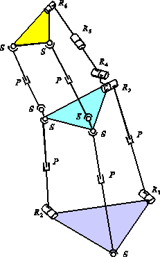
Figure 1. The hybrid manipulator
Tanio K. Tanev
Central Laboratory of Mechatronics and Instrumentation,
Bulgarian Academy of Sciences
Acad. G. Bonchev Str. Bl. 1, Sofia - 1113, Bulgaria
E-mail: tanio@bgcict.acad.bg
Abstract
This paper presents a singularity analysis of a new hybrid (parallel-serial) robot manipulator. The manipulator consists of two serially connected parallel mechanisms. An approach to kinematic modeling of this hybrid manipulator is proposed. The presented singularity analysis is based on the properties of the Jacobian matrices associated with this robot. Several kinds of singularities are identified.
Key words: singularity, kinematics, hybrid manipulator,
parallel
manipulator
1. Introduction
The hybrid manipulation system is a combination of closed-chain
and open-chain mechanisms or it is a sequence of parallel mechanisms. The
hybrid manipulators overcome the limited workspace of the parallel manipulators
and can provide features of both serial and parallel manipulators. Hybrid
manipulators posses the advantages of both serial and parallel manipulators
from rigidity and workspace point of view.
Currently, there has been an increasing interest in the hybrid robot
manipulators although comparatively little literature on these manipulators
is available. Different kinds of hybrid manipulators were studied by several
researchers [1] – [5].
It is well known that in singular configuration the end-effector of
a serial manipulator loses at least one degree of freedom, while the end-effector
of a parallel manipulator ‘gains’ one or more degrees of freedom and becomes
uncontrollable. In context of hybrid manipulators, the singular configurations
can be induced on one hand by the singularities of parallel mechanisms
and on the other hand by the singularities of the serial arrangement of
the parallel mechanisms. These singularities may occur within the Cartesian
workspace and not needfully at its boundaries. Therefore, it is important
from design and control point of view to identify these singularities.
The singular configurations of serial manipulators were studied by
several researchers (see for example [6]-[9]). Some papers were dedicated
to singularities of parallel manipulators [10]-[17]. The determination
of the singularity loci of parallel manipulators is given in [11] and [17].
Merlet [14], [16] used Grassmann geometry to obtain the singular configurations
of parallel manipulators.
Since the concept of hybrid manipulators is quite recent many theoretical
problems have to be solved. In this paper, a new type of hybrid (parallel-serial)
manipulator consisting of two serially connected parallel mechanisms is
proposed. An approach for singularity analysis of this manipulator is presented.
2. STRUCTURE AND COORDINATE SYSTEMS
| The considered hybrid robot manipulator (Fig.1) consists of two serially connected parallel mechanisms. Each mechanism has three degrees of freedom. The overall degrees of freedom for the robot are six. The lower parallel mechanism has three legs with different structures: SPS, R2^P^ S, R1^P^ R3. The upper parallel mechanism has two identical legs with SPS structure and a R4^R5^R6 leg. In this case, the axes of the R3 and R4 revolute joints are perpendicular. The three prismatic joints of the lower mechanism and the two prismatic joints and the R5 revolute joint of the upper mechanism are active (actuated). |

Figure 1. The hybrid manipulator |
A simplified scheme of the robot with attached coordinate frames is
shown in Fig.2.
| The axes of the revolute joints R3 and
R6
are perpendicular to the legs A3B3
and B3D3, respectively. They are coincident
with the lines B3B2 and D3D2,
respectively.
The reference coordinate frame XYZ is attached to the base and its origin is at point A3. The OX axis is collinear with the line A3A2. The coordinate frames O1X1Y1Z1 and O2X2Y2Z2 are attached to the A3B3 leg. The coordinate frame O3X3Y3Z3 is attached to the middle moving platform. The O3X3 axis is collinear with the line B3B2. The coordinate frames O4X4Y4Z4 and O5X5Y5Z5 are fixed to the two links of the B3D3 leg, respectively. In this case, the axes of the revolute joints R3 and R4 are perpendicular and their origins are coincident. The last coordinate frame O6X6Y6Z6 is attached to the upper moving platform (end-effector), so that the axis of rotation (O6X6) is directed along the line D3D2. Therefore, the corresponding transformation matrices can be written as: |
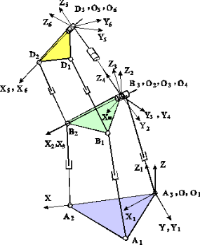
Figure 2. The schematic configuration of the manipulator with coordinate systems |
 , ,  , ,  , ,
 , ,  , ,  , , |
(1) |
where si and ci (i=1,2,3,4,5)
indicate sin(qi) and cos(qi)
, respectively; L3 = A3B3;
L6
=
B3D3.
The transformation matrix for the considered hybrid robot manipulator
can be written as follows:
3. KINEMATIC MODELING
This section presents the kinematic equations, associated with the considered
hybrid robot manipulator. A closed-form solution to the forward position
problem is obtained. The position of the end-effector with respect to the
reference coordinate frame can be expressed as follows:
3.1. FORWARD DISPLACEMENT ANALYSIS OF THE LOWER PARALLEL MECHANISM
The coordinates of points Ai and Bi
(i=1,2) in the OXYZ and O3X3Y3Z3
coordinate frames, respectively, are as follows:
For the position vectors OBi (i=1,2)
with respect to the base coordinate system can be written:
The leg lengths L1 and L2 (L1
= A1B1 , L2 = A2B2)
can be expressed as:
where ![]() denotes the Euclidean norm.
denotes the Euclidean norm.
The following two equations in two unknowns (angles q1
and q2) can be obtained from equation
(9):
f1 s1 + f2 c1 + f3 s2 + f4 c2 + f5 s1 s2 + f6 = 0 , (11)
Obviously, from equation (10) we can derive angle q1.
Thus, manipulating equation (10) and making trigonometric substitutions,
we get the solution of equation (10), i.e.,
 .
(12)
Note that two possible solutions for the angle q2
have been obtained, corresponding to the plus or minus sign in (12).
Therefore, after deriving the angle q1,
equation (11) can be rewritten as:
Now, equation (13) is of the same form as (10) and so can be solved
in a similar way, i.e., equation (13) yields the following solution for
q2
:
 .
(14)
The plus or minus sign in (14) leads to two different solutions
for
q2. Apart from that, equation
(14) involves two different solutions for q1
and that is why the overall number of solutions for q2
is four. Having derived angles q1
and q2, we can form the transformation
matrix AM1. This completes the solution of the forward
position problem for the lower parallel mechanism.
3.2. FORWARD DISPLACEMENT ANALYSIS OF THE UPPER PARALLEL MECHANISM
The solution of the forward displacement problem for the upper parallel
mechanism (Bi - Di) can be obtained
using a similar to the above mentioned approach. The coordinates of points
Bi
and Di (i=1,2) in the O3X3Y3Z3
and O6X6Y6Z6
coordinate frames, respectively, are as follows:
The position vectors ODi (i=1,2)
with respect to the coordinate frame OXYZ can be written as:
Then, the leg lengths L4 = B1D1
and L5 = B2D2 can
be expressed as follows:
Two equations in two unknowns (angles q3
and q5) can be obtained from equation
(20), i.e.,
v1 = 2bL6; v2
= 2 bd c4; ![]() ;
;
w1 = -2b1x L6 ;
w2
= -2 b1x d1x c4
;
w3
= 2 d1y L6 ; w4 =
-2 b1y d1y c4
;
w5 = -2b1x d1y ;
w6
= 2b1x d1y s4
; ![]() ;
;
L6 = B3D3 .
Equation (21) gives the solution of the angle q3
, i.e.,
 .
(23)
Having derived angle q3, equation
(22) can be rewritten as:
Equation (24) yields the following solution for q5
:
 .
(25)
Equations (23) and (25) give four different solutions of the forward
displacement problem for the second (upper) parallel mechanism. Now, the
transformation matrix A can be formed, which completes the solution
of the forward displacement problem for the considered hybrid robot manipulator.
Each parallel mechanism has four solutions for the forward position problem
and therefore, each mechanism has four assembly modes.
For details about the solutions of forward and inverse kinematic problems
see [3]. An example for the solution of the inverse position problem is
shown in Fig.3., where the presented animation shows a tracing a circle
by the end-effector with a constant orientation.
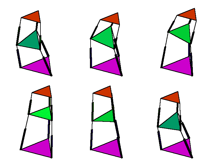
Figure 3. Tracing a circle by the end-effector with a constant orientation
4. THE JACOBIAN MATRICES
In this section, the velocity equations for the considered hybrid manipulator
are derived. The time-derivative of the constraint equations (9) and (20)
yields:
 ,
(27)
,
(27)Now, if we consider only the ‘serial part’ of the manipulator (i.e.,
the time-derivative of the equation (3) and A-matrices) we can write
the following:
5. SINGULARITY ANALYSIS
Referring to equation (30), the conditions that the hybrid manipulator is in a singular configuration is given by:
Now, we will analyze these kinds of singularities.
5.1. SINGULARITIES No. 1
The first kind of singularities is associated with the parallel mechanisms
and occurs when the following condition is satisfied:
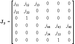
The obtained determinant of the matrix JP can
be written as follows:
Hence, the singularity occurs when at least one of the elements
(jnm) of the right side of equation (32) is equal to
zero. Therefore, the first kind of singularities will be composed of four
subsets, which will be considered below.
5.1.1. Singularity of type 1.
This type of singularities occurs when:
Therefore, equation (35) is the condition for the considered type
of singularities. Obviously, this kind of singularities is associated with
the lower parallel mechanism. An example of a singular configuration of
type 1 of the lower parallel mechanism is shown in Fig.4.

Figure 4. Singular configuration of the lower parallel mechanism
(singularity of type 1)
It is known that a singularity for a parallel manipulator occurs when
two solutions of the direct position problem meet. We will proof this statement
for this kind of singularities. Two solutions of the direct problem will
meet when the square root of equation (12) is equal to zero, i.e.,
5.1.2. Singularity of type 2.
This type of singularities occurs when:
The singularity surfaces can be plotted using equations (39) and (12) and they are shown in Fig.5. These singularity surfaces are functions of the leg lengths. The singularity surfaces of the other types of singularities can be plotted using a similar approach, but for the sake of brevity they are not shown in the paper.

Figure 5. Singularity surfaces for the singularity of type 2.
Fig.6 shows an example of a singular configuration of type 2 of the lower parallel mechanism.

Figure 6. Singular configuration of the lower parallel mechanism
(singularity of type 2)
The singularities of type 1 and type 2 are associated with lower parallel
mechanism. The next two types of singularities refer to the upper parallel
mechanism.
5.1.3. Singularity of type 3.
This type of singularities occurs if the following condition is satisfied:
Likewise the lower parallel mechanism, it can be proofed that the singular
configuration occurs when two solutions of the direct position problem
meet. The proof is similar to the one given in section 5.1.1.
5.1.4. Singularity of type 4.
This type of singularities occurs when:
Here, design singularities and configuration singularities are possible:
Solving equations (44) and (24) together yields:
Singularities of types 1 and 2 are associated with the lower parallel
mechanism, while the singularities of types 3 and 4 are associated with
the upper parallel mechanism. The schemes for singularities of types 3
and 4 are similar to the ones of types 1 and 2, respectively, and for this
reason they are not shown graphically in the paper.
5.2. SINGULARITIES No. 2
This kind of singularities is associated with the serial arrangement
of the two parallel mechanisms, i.e., the singularities No. 2 occur when
the following condition is satisfied:
Referring to equation (47), two possible cases of singularities
can be found, which will be considered bellow.
5.2.1. Singularity of type 5.
This type of singularities occurs by the following condition:
This type of singular configuration is illustrated in Fig.7.
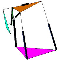
Figure 7. Singular configuration of type 5
5.2.1. Singularity of type 6.
The condition of this type of singularity is the following:

Figure 8. Singularity surface for the singularity of type 6.
This completes the singularity analysis of the considered hybrid manipulator.
6. CONCLUSION
The kinematic and singularity analyses of a new type of hybrid manipulator
are presented in this paper. An approach to kinematic modeling of this
hybrid manipulator is proposed. A closed-form solution of the forward position
problem for the considered manipulator is obtained. Several types of singularities,
which are associated with the parallel mechanisms and with the serial arrangement
of these mechanisms, are identified. Due to the hybrid architecture of
this manipulator, singular configurations are caused not only by the singularities
of the parallel mechanisms but as well as by the singularities of the serial
arrangement of the parallel mechanisms. The obtained results are graphically
illustrated. The identification of the singularities of the manipulator
is important from design and control point of view.
ACKNOWLEDGMENTS
Warm thanks are due to Dr D.R. Kerr (University of Salford, UK)
and University of Salford, United Kingdom, where similar parallel mechanisms
with three degrees of freedom were generated and where the author spend
nine months of 1995 as a visiting fellow.
REFERENCES