Table 2 shows what the MecaGRID configuration would resemble using only the clusters with public IP addresses (486 processors). Shown in Table 3 is the present MecaGRID configuration that uses private IP addresses. The clusters at CEMEF and the IUSTI have private IP addresses which necessitated the creation of a Virtual Private Network (VPN) or tunnel to pass messages between the different clusters. The INRIA clusters have public IP addresses but the VPN treats them as if they were private.
The maximum number of processors available at the CEMEF and the IUSTI is 92 (each site
uses two processors for system management).
|
The Random Access Memory (RAM) is the total RAM available to the Node
thus, approximately 1/2 is available to each CPU of the Node for Nodes
with bi-processors.
Note that with the exception of the IUSTI, all the clusters have two CPUs/Node.
Thus the INRIA-nina (or simply nina) and the IUSTI clusters both have 2 GHz processors, nina
with 1/2 GB RAM/CPU and the IUSTI with 1 GB/CPU.
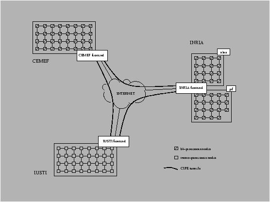
The VPN establishes routes through the Grid and tunnels between frontends in order to provide connectivity between the frontend nodes; all the frontends have public IP address. Each pair of frontends is connected via a tunnel in which crypted and encapsulated packets are transmitted. The packets are compressed to improve the flow rate through the tunnel. The VPN is completed by the addition of routes so that each processor can send a packet to any other processor on the Grid and see each frontend as a default gateway for external addresses (i.e. not on the same LAN). A packet sent from an INRIA processor to a CEMEF processor is first sent to the INRIA's frontend where special routes have been set up to send it in the appropriate tunnel. The VPN functions as if all processors were on a WAN (wide area network) - see Nivet [#!nivet1!#]. Figure 3 ( from Nivet [#!nivet1!#]) shows a schematic of the VPN for the present MecaGRID configuration. For additional technical details on the MecaGRID the reader is referred to Nivet's report.