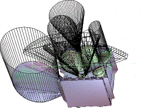
| The layout of antennas and observation instruments on the outer walls of a satellite is extremely constrained, because a satellite is desired to be constructed as compactly as possible. |
 |
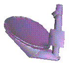 |
An antenna, in general, consists of a parabolic reflector and a source that either emits or receives a signal, and their supporting structures. It also has a field of vision, that can be shaped more or less as a cone. A field of vision must not be obscured by an obstacle, which means that this cone is not intersected. |
We start the layout from scratch, adding the instruments one by one. At each step, the problem consists in placing one instrument in a polyhedral environment.
We study here non mobile antennas. The attitude of such an antenna is determined by a three-dimensional vector specifying the position of a reference point of the antenna, and an angle specifying the rotation around the axis of its parabolic reflector, which is its direction of vision and therefore is fixed. Thus the placement has four degrees of freedom.
However the rotation and the component of the translation vector in the direction orthogonal to the wall we are placing the instruments on are less important and in general a crude discretization of the ranges of these two degrees of freedom suffices. So, at each step we only consider the placement of one instrument by translation in a plane.
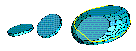
| The set of all allowed translations in the plane (the admissible
space) that place an instrument so that it does not collide with
the environment is a planar section of the three-dimensional Minkowski
difference of the environment and the object.
Though the worst case size of the section is quadratic, as well as the difference itself, usually the size of the section is much smaller. It can be linear while the three-dimensional Minkowski difference is quadratic. |
 |
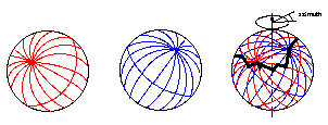 |
Both instrument and environment are decomposed as unions of convex polyhedra. The section of the Minkowski difference of two convex polyhedra corresponds to a path on the sphere in the superposition of the Gaussian diagrams of the two polyhedra, and this path is monotonic in the azimuth. The algorithm computes the path using this property. |
In this way, we directly compute a planar section of a Minkowski difference, without computing the entire Minkowski difference. Thus we get an optimal output-sensitive algorithm for computing the admissible space.
Degeneracies, such as coplanar facets in the polyhedra, and so on, are explicitely handled.
Numerical precision problems when evaluating geometric tests are
solved using a
method
computing exactly the signs of determinants.
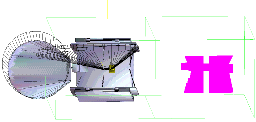
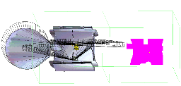
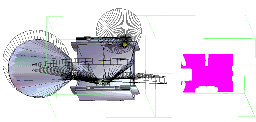
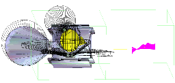
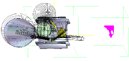
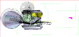
The following images represent a possible sequence of placements. At each step, the physical part of the piece being placed is drawn in yellow. The boundaries of the fields of vision are represented as slashed areas. The admissible space is drawn in magenta on the right. A white point is shown in this admissible space, which corresponds to the current position chosen for the yellow instrument.
Click on the image to get a larger version
|
|
|
|
|
|
Aide géométrique à l'aménagement de satellites by Eelco de Lange - PhD Thesis
postscript file
Slices of Minkowski differences and Satellite Antenna Layout by Jean-Daniel Boissonnat, Eelco de Lange and Monique Teillaud
with color pictures postscript file 13.2Mb, compressed 5.5Mb.
with black and white pictures postscript file 5Mb, compressed 3Mb.
with no pictures postscript file 1.1Mb, compressed 0.15Mb.
| Last modified: Tue Aug 29 11:12:30 MET DST 2000 | Monique Teillaud | Thèmes |
|
Français |