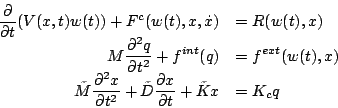
The first kernel considered in this study is the software AERO developed at the University of Colorado with the collaboration of INRIA - see Dervieux [#!derv1!#], Konga and Guillard [#!BNkonga_HGuillard_1994!#], Farhat [#!farhat1!#], and Martin and Guillard [#!RMartin_HGuillard_1996!#] for details. AERO relies on an unsteady three-field model consisting of a structural model (AERO-S), a fluid model (AERO-F), and a pseudo-elasticity model (AERO-E) for the dynamical fluid mesh. It is useful for the sequel to give a few equations describing the coupled model:
where ![]() designates time,
designates time, ![]() the position of a moving fluid grid
point,
the position of a moving fluid grid
point, ![]() is the fluid state vector,
is the fluid state vector, ![]() results from the finite-element/volume
discretization of the fluid equations,
results from the finite-element/volume
discretization of the fluid equations, ![]() is the vector of
convective ALE
fluxes.
is the vector of
convective ALE
fluxes. ![]() is the vector of diffusive fluxes,
is the vector of diffusive fluxes, ![]() is the structural
displacement vector,
is the structural
displacement vector, ![]() denotes the vector of internal forces in
the
structure, and
denotes the vector of internal forces in
the
structure, and ![]() the vector of external forces.
the vector of external forces. ![]() is the finite-element
mass matrix of the structure,
is the finite-element
mass matrix of the structure, ![]() ,
, ![]() and
and ![]() are
fictitious mass, damping and stiffness matrices associated with the
moving
fluid grid and
are
fictitious mass, damping and stiffness matrices associated with the
moving
fluid grid and ![]() is a transfer matrix that describes the action of
the
motion of the structural side of the fluid/structure interface on the
fluid
dynamic mesh.
An implicit finite-element time scheme is used for the structural
model and an implicit time-staggered scheme for the
structure. A vertex-centered upwind finite-volume scheme is employed
when AERO-F is used in the fluid-only mode.
Numerical options address second-order accuracy both in space and time
- see Dervieux [#!derv1!#], Konga and Guillard [#!BNkonga_HGuillard_1994!#],
Farhat [#!farhat1!#], and Martin and Guillard [#!RMartin_HGuillard_1996!#].
is a transfer matrix that describes the action of
the
motion of the structural side of the fluid/structure interface on the
fluid
dynamic mesh.
An implicit finite-element time scheme is used for the structural
model and an implicit time-staggered scheme for the
structure. A vertex-centered upwind finite-volume scheme is employed
when AERO-F is used in the fluid-only mode.
Numerical options address second-order accuracy both in space and time
- see Dervieux [#!derv1!#], Konga and Guillard [#!BNkonga_HGuillard_1994!#],
Farhat [#!farhat1!#], and Martin and Guillard [#!RMartin_HGuillard_1996!#].
The goals of this study were: 1) Creation of the MecaGrid, 2) Studing the efficiency of the one-phase AERO-F code using the MecaGRID, and 3) Developing and examining the efficiency of a three-dimensional two-phase version of the AERO-F code for Grid applications. The results of these experiments are reported in the sections that follow.