Central Processing Unit Simulation
Purpose: To explore various architectures of CPU through their programming and their step-by-step execution.
Realization: Pure Tcl-Tk implementation. Requires Tcl-Tk version higher than 8.2 and the BWidget ToolKit (Unifix). Tested on Window2000 and Linux.
Contact: Written by Charles ANDRÉ, Electrical Engineering Department, Faculty of Sciences, University of NICE-SOPHIA ANTIPOLIS. andre@unice.fr
Caveats: The look and Feel of the widgets is dependent on the operating system. The pictures given in this text are screen copies captured under Windows 2000.
Be sure that Tcl-Tk, version 8.3 or higher is installed.
Define an environment variable called SOFTDIR that contains the path to a directory tools. Add $SOFTDIR/bin in the PATH variable.
Do not modify the names of the directories. All the programs provided by the author must be installed under the tools directory.
Unpack Tcl-Tk’s common files in tools/tcl and specific files in tools/ARCHI.
There is no need to detail the tools/tcl directory.
The ARCHI directory contains 4 subdirectories:
· bin
· TCL
· EXAMPLES
· doc
Once the various Tcl-Tk files are installed, you still have to configure your own environment: Execute platform a script that copies customized configuration files in your Home Directory.
Execute CPUSimulator. This is a symbolic link, present in the $SOFTDIR/bin directory and pointing to the actual application: $SOFTDIR/ARCHI/bin/CPUSimulator.tcl.
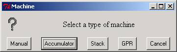
The dialog box below appears.
Four machines are proposed:
Remark: GPR machine are not yet implemented.
These machines are very small machines: They have tiny memories and a limited set of instructions. For simplicity, data memory and instruction memory are separated.
Click on the corresponding button to select the desire machine type.
The default sizes of the (small) memories of the machines are stored in a configuration file ( .CPUSimulator, in your home directory). This size is initially set to 15. A dialog box proposes to change these sizes. You can answer “No”, since the actual sizes could be enlarged later.
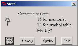
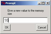
If a modification is selected, another dialog box pops up and asks for a new value.
“Memory” applies only to Data and Instruction Memories; “Symbol” concerns the size of the Table of Symbols; “Both” applies to both. Prefer this latter option to the previous two choices.
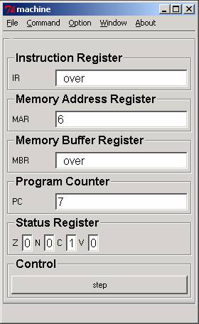
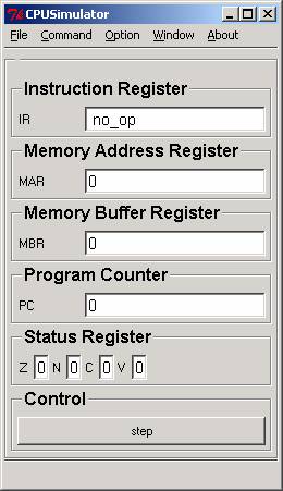
The control window is the main panel. It offers
· a menu bar,
· various registers,
· and a control button
The menu bar presents a set of button-like menu entries to users. When you drag your mouse over the menu bar, the different menus are displayed. A click on a button posts (i.e., displays) the associated menu.
|
File |
||
|
Load |
open a browser for loading |
|
|
Re-load |
load the previously loaded file |
|
|
Save |
open a browser for saving |
|
|
Exit |
exit the application |
|
|
Command |
||
|
Reset |
reset the simulation (memory and register cleanup) |
|
|
------------------------ |
||
|
Extend Memory |
increment the size of the data and instruction memory by 1 |
|
|
Option |
||
|
Preferences |
configure your personal environment with a dialog box |
|
|
------------------------ |
||
|
Fonts |
show and select fonts |
|
|
------------------------ |
||
|
Help font: 8pt |
set the size of font in balloon to 8 |
|
|
Help font: 10pt |
set the size of font in balloon to 10 |
|
|
Help font: 12pt |
set the size of font in balloon to 12 |
|
|
------------------------ |
||
|
Step |
running mode: step by step (a full instruction at a time) |
|
|
Fetch/Execute |
running mode: separate instruction fetch and execution |
|
|
Detail |
running mode: details (i-fetch, decode, d-fetch, operate, store) |
|
|
Window |
check buttons selecting windows to show/hide |
|
|
Show ALU |
||
|
Show Symbol Table |
||
|
Show Pseudo Console |
||
|
Instruction Set |
||
|
Performances |
||
|
Raise Memory |
||
|
About |
miscellaneous information |
|
|
Author |
||
|
Address |
||
|
Version |
||
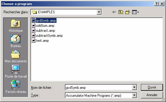
This dialog box is similar to the file loading dialog box. Contrary to the file loading box, creating a new file is possible.
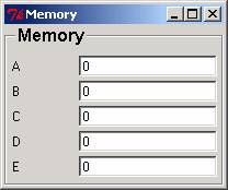
Registers displayed in the control window are non user-programmable registers. They are useful for tracing program executions and understanding data paths.
This button indicates what is the next thing to be done by the simulator. Its label depends on the current running mode.
This dialog box allows the user to customize its environment. His/her choices are saved in a hidden file: .CPUSimulator in his/her home directory.
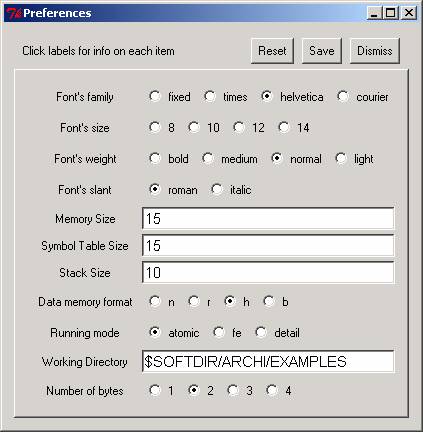
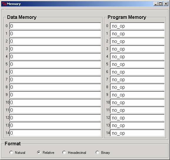
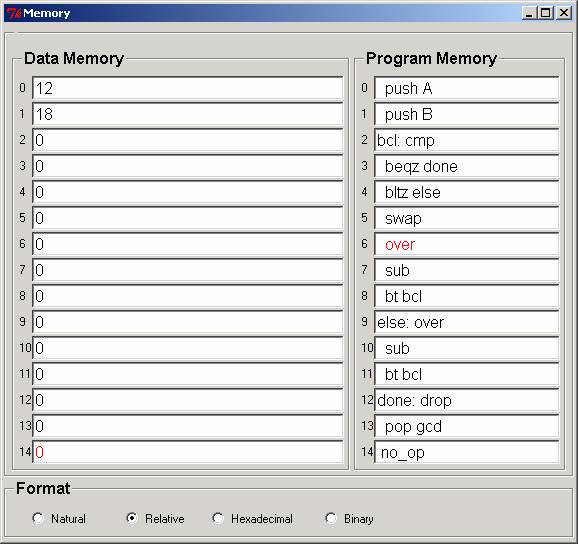
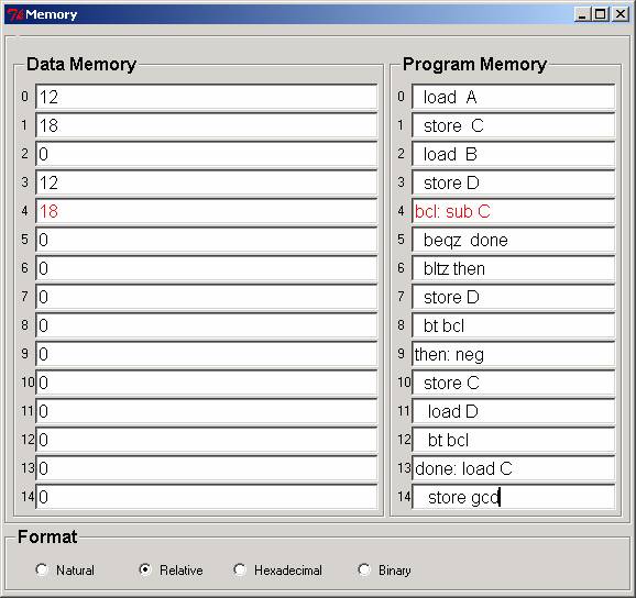
The left side of the window represents the Data Memory, the right side the Program Memory. The addresses are written on the left of each memory entry.
The bottom frame, entitled “Format”, allows the user to select a display format.
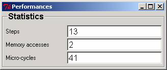
While a program is executed, statistics are computed. The number of steps (i.e., the number of executed instructions), the number of Memory Accesses, and the number of microcycles are automatically updated. All the counters are reset to 0 by the Reset command, or by a new program loading.
The number of microcycles by instruction is computed by taking one unit for each phase: i-fetch, decode, d-fetch, operate, d-write. This is a coarse approximation. With modern fast CPUs, external accesses should be given a relative cost much higher than 1.
When your program uses symbolic names, you have to fill up the symbol table (You do what is usually done by an assembler!).
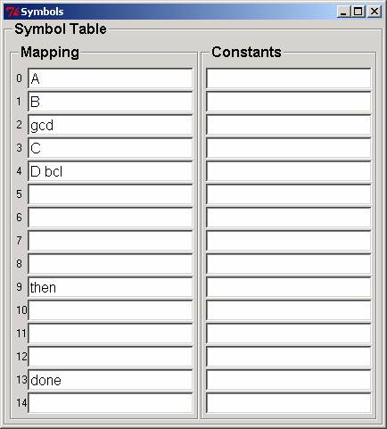
The above table corresponds to a program that makes reservation for variables A, B, gcd, C, and D at the respective addresses 0, 1, 2, 3, 4 in the Data memory. The program uses symbolic labels “bcl:”, “then:”, “done:” at respective locations 2, 4, and 13 in the Program Memory.
Aliases are possible: each entry may contain a space-separated list of identifiers.
Syntactic Remark: symbolic labels are followed by a colon in their definition; the colon is omitted in the table and in the branch instructions.
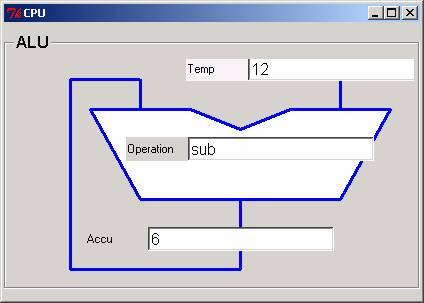
As explained above, this is not a programmable machine. The user has to drag and drop the data, select the operation of the ALU, apply the operation and collect the result.
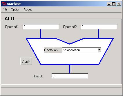
This machine has an accumulator, used as both the first operand of the operation performed by the ALU, and the result of the operation. The second operand, if any, comes from the Memory or the Instruction Register (for immediate operations). The entry named “Temp” shows the value of this operand.
The operation entry is set during the decode phase according to the contents of the Instruction Register.
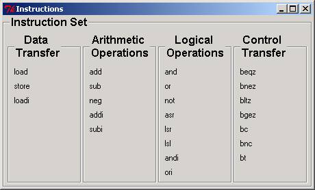
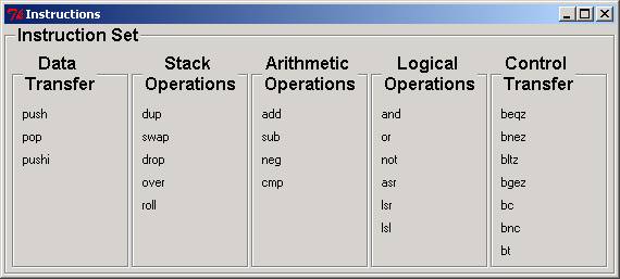
The (simplified) instruction set is available in the Instruction Set Window. The semantics of each instruction is popped-up when the mouse stays over the label for a while.
This program computes the Greatest Common Divider of two positive integers A and B. This algorithm is the original one, using only subtraction, not the remainder of the integer division.
Gcd is the result, A and B are the input data preserved during the computation. C and D are auxiliary variables.
|
load |
A |
|||
|
store |
C |
; |
C is the dynamic value of A |
|
|
load |
B |
|||
|
store |
D |
; |
D is the dynamic value of B |
|
|
bcl: |
sub |
C |
; |
D - C |
|
beqz |
done |
; |
If Z then go to done |
|
|
bltz |
then |
; |
If D < C then go to then |
|
|
store |
D |
; |
D > C => B <- B - A |
|
|
bt |
bcl |
; |
iterate |
|
|
then: |
neg |
; |
C > D; take the opposite of D - C |
|
|
store |
C |
; |
C <- C - A |
|
|
load |
D |
; |
Before looping, put D in the accumulator |
|
|
bt |
bcl |
; |
iterate |
|
|
done: |
load |
C |
; |
Here C=D=gcd |
|
store |
gcd |

The figure above shows the control window before executing the instruction at location 5 (i.e., the contents of PC). In the Program Memory Window, the last executed instruction (bcl: sub C) is highlighted (painted red) and still present in the Instruction Register. The Memory Address Register points to (data) memory cell 3 (i.e., the location of C, the last accessed memory cell). The Memory Buffer Register contains the value of C (i.e., 12).
The highlighted Data Memory cell is the more recently written memory cell (Here, the cell that stores the value of D).
Remind that correspondences between memory locations and symbolic names are given by the Table of Symbols.
The UAL has two operands and a result. Sources and destination are the stack. The stack itself is represented on the left of the picture. The stack grows upwards.
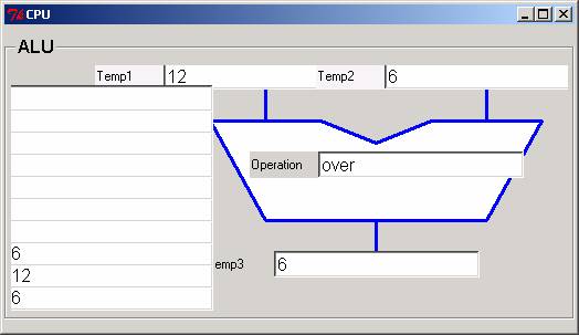
The instruction set is available in the Instruction set Window. The semantics of each instruction is popped-up when the mouse stays over the label for a while.
|
push |
A |
; |
A |
- |
|||
|
push |
B |
; |
A |
B |
- |
||
|
bcl : |
cmp |
; |
A |
B |
- |
Set N and Z |
|
|
beqz |
done |
; |
Branch to done if A == B |
||||
|
bltz |
else |
; |
Branch to else if A < B |
||||
|
swap |
; |
B |
A |
- |
|||
|
over |
; |
B |
A |
B |
- |
||
|
sub |
; |
B |
A-B |
- |
|||
|
bt |
bcl |
; |
Branch to bcl with new A and old B |
||||
|
else: |
over |
; |
A |
B |
A |
- |
|
|
sub |
; |
A |
B-A |
- |
|||
|
bt |
bcl |
; |
Branch to bcl with new B and old A |
||||
|
done: |
drop |
; |
A |
- |
Discard B |
||
|
pop |
gcd |
; |
- |
||||