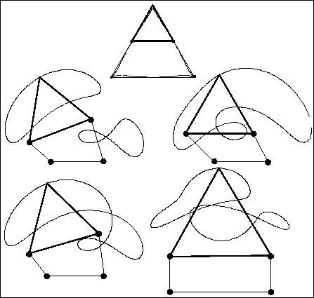
4barres enables to visualize the motion of a four bar mechanism, which may have a coupler, together with its velocity graph.
Free source codes are available under Free Software Society conventions through anonymous ftp here.
This software is provided "as is" without warranty of any kind. In no event shall INRIA be liable for any loss of profits, loss of business, loss of use or data, interruption of business, or for indirect, special, incidental, or consequential damages of any kind, arising from any error in this software. No commercial use of this software can be made without the previous agreement of INRIA. The use of this software for any publication should acknowledged the contribution of INRIA.
Window system: X
Type: sources
Language: C
Number of lines: 3200
Size of binary: 0.76 Mo
Output: display, files, graphic output in xjpdraw format
4barres user's manual
Version 0.1
July 26, 1995
J-P. Merlet
INRIA Sophia-Antipolis
France
E-mail: Jean-Pierre.Merlet@inria.fr
This program enables to visualize the motion of a four bar mechanism, which may have a coupler, together with its velocity graph.
The mechanism is defined in a structure:
struct quatre_barres
{

	float p;
	float r;
	float s;
	float c;
	short int coupler; /* 1 if the coupler exists */
	float a;
	float b;
	float sgamma; /*sine and cosine of gamma */
	float cgamma;
};
where the element of the structure are defined in figure 1.
A file defining a four bar mechanism has the following syntax:
4-barres
p
r
s
c
coupler (1)
a
b
sgamma
cgamma
The coupler may not be defined in which case the reference point C is taken at the extremity of the link of length r. In that case coupler is put to 0 and there is no need to define a, b, sgamma, cgamma.
After the definition of the mechanism you can introduce the coordinates of precision points which may have been used for defining the mechanism. A precision point is defined by the three numbers PHI XC YC. In that case the location of the precision points will be displayed on the coupler curve.
To run the program use the command:
4barres [mechanism file]The mechanism will be displayed in a nominal position (chosen in general such that the link of length c is horizontal).
This button enable to animate the mechanism: the two branches of the trajectory of C will be drawn successively. After the animation the trajectories of C will be displayed on the screen, one in red, the other in blue. The other buttons will be used to display either the first or second branch only. In that case the location of the point C will be indicated on the coupler curve for various values of PHI separated by a constant difference.
The animation speed can be adjusted using the Animation step button which specify the increment angle on the angle PHI used between two displays of the mechanism. A smaller angle will slow the animation.
These buttons may be used to modify the location of point OA on the screen or to zoom the drawing. To zoom give a scale factor followed by a Return in the Zoom window. A number lower than 1 will enable to reduce the size of the display. To indicate a new position of OA give its new screen coordinates in the window, followed by a Return.
To help you to determine the best location of the origin, the x, y window display the coordinates of the current mouse position, both in screen coordinates and in the mechanism coordinates (whose origin is at the point OA).
With this button you can display the mechanism in the two configurations defined for a given angle PHI. The set of coordinates of C are displayed, together with the corresponding PSI angle.
This button has a menu which will appear when clicking with the right mouse button. This menu is used either to display the velocity graph (velocity of C as a function of the input angle PHI or to save a result in graphical form using a format which can be used with the xjpdraw graphic editor (which is available via anonymous ftp).
Using the first item of the menu a drawing of the mechanism in the current position will be saved in the file pos.jpd.
Using the second item of the menu the full coupler curve of the mechanism will be saved in the file curve.jpd.
The third and fourth items of the menu are used to display the velocity graph (velocity of C as a function of the input angle PHI) for each different branches. At the same time the velocity curve will be saved in xjpdraw format in the file vxi.jpd, vyi.jpd, vvi.jpd where i represent the branch number 1 or 2. Note that you can modify the nominal velocity of the actuated joint by giving a new value in the motor velocity window, followed by a Return.
With items 5 and 6 you will save a branch of the coupler curve in the file curve1.jpd, curve2.jpd.
The last item of the menu is used to save in the files anim1.traj, anim2.traj the coordinates of C as a function of the input angle PHI. On a line of these files you will have PHI XC YC where PHI is given in degree.
To use one of the graphical output files, e.g. pos.jpd use xjpdraw with the command line:
xjpdraw -X 6 -Y 6 -F pos.jpdwhere the numbers followng the X and Y argument are the width and height of the box which will contain the output data.
Here is an example of output:
