5barres enables to compute and visualize the solution of the forward kinematics of a 3-RPR planar parallel robot.
Free source codes are available under Free Software Society conventions through anonymous ftp on: ftp-sop.inria.fr in the coprin/FK/3-RPR directory.
This software is provided "as is" without warranty of any kind. In no event shall INRIA be liable for any loss of profits, loss of business, loss of use or data, interruption of business, or for indirect, special, incidental, or consequential damages of any kind, arising from any error in this software. No commercial use of this software can be made without the previous agreement of INRIA. The use of this software for any publication should acknowledged the contribution of INRIA.
Window system: X
Type: sources
Language: C
Number of lines: 3200
Size of binaries: 0.915 Mo
Output: display, files, graphic output in xjpdraw format
5barres user's manual
Version 0.1
July 26, 1995
J-P. Merlet
INRIA Sophia-Antipolis
France
E-mail: Jean-Pierre.Merlet@inria.fr
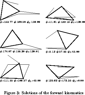
This program enables to compute and visualize the solution of the forward kinematics of a 3-RPR planar parallel robot. Such a robot is constituted of a moving platform connected to the ground through three revolute-prismatic-revolute kinematic chains (figure 1). The prismatic joint of each chain is actuated and the problem to solve is to find the position of the moving platform according to the the three lengths of the chains. This program enables to compute the angles phi, psi, psi3 solutions of the forward kinematics.
The forward kinematics has at most 6 different solutions,
see [2],[1],[3]. To solve this
problem we have to solve a system of three non-linear equations in
three unknowns. Here we reduce this system to an univariate polynomial
of order 12 (although a polynomial of order 6 may be found numerical
robustness seems to be better with a higher order polynomial).
This polynomial is solved using a numerical procedure.
Note that the forward kinematics of other planar parallel robots, like the
3-RRR robot, can be reduced to solving the forward kinematics of a 3-RPR
robot.
The mechanism is defined via two structures:
struct quatre_barres
{

	float p;
	float r;
	float s;
	float c;
	short int coupler; /* 1 if the coupler exists */
	float a;
	float b;
	float sgamma; /*sine and cosine of gamma */
	float cgamma;
};
struct cinq_barres
{
	struct quatre_barres sous_4barres;
	float or[2];
	float r3;
}
Indeed the 3-RPR robot is constituted of a four bar mechanism
whose elements are defined in figure 2, with an additional
link whose attachment point to the ground A3 has coordinates stored
in or and whose length is r3.
Therefore the three lengths of the chains are .
To use this program you need to define the structure of the robot in a
file with the following syntax:
5-barres
p
r
s
c
1
a
b
sgamma
cgamma
or[0]
or[1]
r3
To run the program use the command:
5barres [mechanism file]If there is at least one solution to the forward kinematics the mechanism will be displayed in a configuration which is solution of the forward kinematics problem.
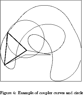
Note that the solutions are defined by the location of B3 which are at the intersection of the coupler curve of the four-bar mechanism A1B1B3B2A2 with the circle centered in A3 and of length r3.
Clicking in this button will display all the solutions of the forward kinematics. The value of the angles will be displayed at the bottom of each solution.
By clicking in this button the four bar mechanism will be animated, then the coupler curve of the four bar mechanism together with the circle described by B3 will be displayed. This enable to verify the number of solutions, which is the number of intersection points of the coupler curve with the sextic. Note that you can slow down the animation speed by giving a small value of the animation step angle in the Animation step button, followed by a Return. The FCoupler button enable to display only the coupler curve and the circle without the animation of the four bar mechanism.
These buttons may be used to modify the location of point A1 on the screen or to zoom the drawing. To zoom give a scale factor followed by a Return in the Zoom window. A number lower than 1 will enable to reduce the size of the display. To indicate a new position of A1 give its new screen coordinates in the window, followed by a Return.
To help you to determine the best location of the origin, the x, y window display the coordinates of the current mouse position, both in screen coordinates and in the mechanism coordinates (whose origin is at the point A1).
In this three buttons you can define new leg lengths for the robot. Positive value should be introduced, followed by a Return. For each new value a solution of the forward kinematics, if any, is displayed.
This button enables to save the result in a graphical format, which can then be used to create drawings using the drawing editor xjpdraw, which is available by ftp.
This button has a menu which will appear when clicking with the right mouse button.
With the first item of the menu you can save all the solutions of the forward kinematics in xjpdraw graphical format. With the second item you can save the drawing of the coupler curve and the circle in the same format.
To use one of the graphical output files, e.g. config.jpd use xjpdraw with the command line:
xjpdraw -X 6 -Y 6 -F config.jpdwhere the numbers following the X and Y argument are the width and height of the box which will contain the output data. Note that for the output of this program you need to always use the same width and height of the box.

