Color Correspondence
The
correspondence issue is one of the essential problems in any 3D acquisition
task, and is more pronounced in the case of the interention under consideration,
because of its structure in addition to the time and accuracy constraints
imposed. The following paragraphs present a detailed explanation of the
proposed solution, its efficiency, and challenges.
Setup
A
proposed setup for producing the desired color discrimination is shown
in Figure 4.1. Three sources of light are placed above the vertebra, on
a straight line along the transverse processes, and all directed towards
the posterior process (Note that only one vertebra is shown). The cameras
are placed along the same straight line as the lights, also directed towards
the posterior process. This setup allows a maximum overlap of the colored
regions, with minimal occlusions.
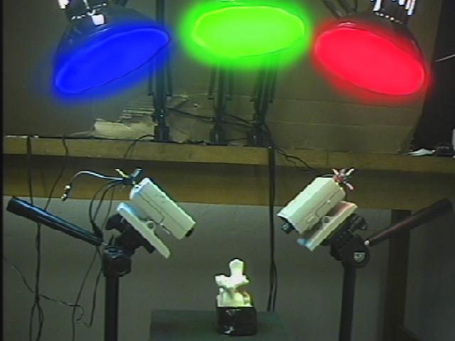
Figure 4.1 Actual Color discrimination
setup on one vertebra.
Illumination
A
crucial requirement for the acquisition setup is the correct illumination.
Several aspects of light, presented next, should be considered when setting
up the illumination system.
AC/DC illumination
If
the normal 50 Hz power line is to be used for supplying the lighting system,
then the light intensity will vary from a maximal value to a minimal one
every 1/200 of a second. On the other hand, the CCD camera system (camera
+ video card) has a maximum frame rate of 1/30 seconds; i.e., it needs
1/30 seconds to process a single frame. Looking more closely into the functioning
of the CCD camera system, the latter can be summarized in two steps:
Light
strikes the CCD array and changes the electronic state of the CCD devices.
The
change of state is translated into an image.
It
can be safely stated that the first step is much faster then the second
one. The implication of all of the above is shown in Figure 4.2. If the
time for the change of state of the CCD elements are represented in red,
different amplitudes of the acquired light would then result (this may
be compared to a stroboscopic effect). In turn, this difference introduces
two more complications:
Although
the amount of the light that enters the camera is automatically normalized
, the resulting images will have different brightness.
The
color temperature of this light will vary, varying with it the colors of
the image, despite the automatic white color balance.
Therefore,
using an AC source would have very detrimental effects on the quality of
the acquired images.
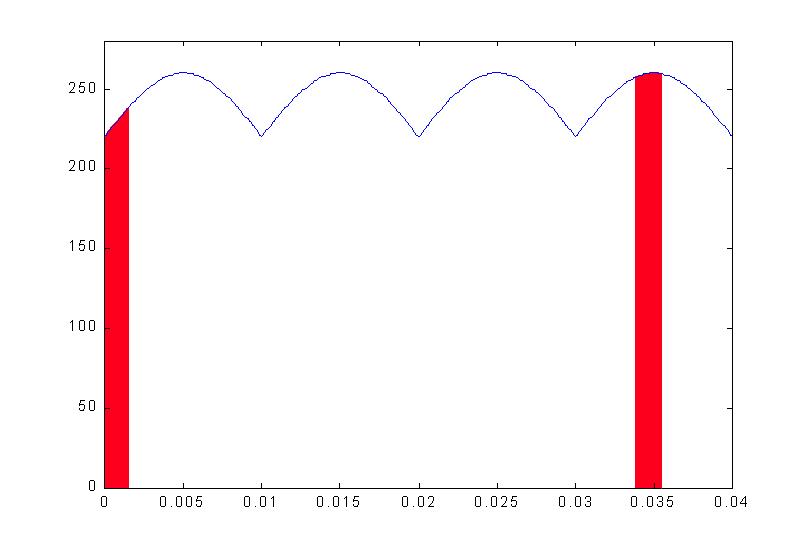
Figure 4.2 Note that the
AC source is not rectified, but a rectified version is represented to imply
the functioning of the lamp that does not distinguish polarities.
The
proposed solution is to use a DC source instead of an AC one, where the
rectifier in Figure 4.3 was used, achieving a ripple of less than 0.5V,
for a rectified DC voltage of 270V.
Figure 4.3 Voltage rectifier
Color temperature
As
mentioned in 3.1.1.3, the color temperature of light is a measurement of
how close it is to white light. Ideally, the illumination scheme would
require a color temperature of about 5000°K, corresponding to a white
(neutral) light. The incandescent lamp produces light of approximately
3000°K. However, when considering Figure 4.4, which shows the power
delivered to the lamp versus the color temperature of the produced light,
it may be argued that a better quality of light will be obtained by increasing
the voltage. Indeed, the supplied 270V DC voltage improves light color.
Figure 4.4 Increasing
the voltage of the lamp to 270V would give a "whiter" color. Plot from
Commission Internationale de l'Eclairage standards for iluumination.
Finally,
it should be noted that although fluorescent lamps are claimed to produce
light as close to white as possible, this is only true for the human perception
of the latter. Experiments with fluorescent light showed a high blue color
content.
Coloring the Light
The
final step in the preparation of the lighting system is to add color to
the light. The following schemes were implemented:
Using
a colored plastic sheet acting as a filter above the light
Using
colored lamps
Airbrushing
the lamps whit several layers of glass paint.
The
second solution delivered the best results. However, some complication
were noted:
If
a glossy abject is illuminated (such as the plastic model used in the experimentation),
the camera will translate some rejoins with a high mix of colors into white
regions. To account for this, a white filter was used on top of the colored
lamps to diffuse the light and break its intensity.
Color Sensing
The
following sections describe the different aspects of the color acquisition
process.
Card Settings
A
mentioned in section 3.1.2.2, there are four settings that could be used
to enhance the quality of the acquired image. The potential benefit of
each is now explored.
Saturation:
Maximizes the color content of the image. The saturation translates how
pure the color is; for instance, pink is less saturated than red.
Hue:
The hue is a measure of the how the color is perceived by an observer,
changing the hue would simply garble the colors within the image.
Brightness:
May be used to account for lighting deficiency or excess, represents a
minimal effect on the overall operation.
Contrast:
Increases spatial discrimination by making light regions lighter and dark
regions darker. The contrast operator acts only on the brightness component
of the color, in other words, it does not affect the color. Indeed, it
only changes the amount of black that is present inside a specific color.
In
general, best results are obtained by fully increasing the saturation,
and interactively increasing the contrast. Figure 4.5 shows the effect
of saturation and contrast enhancement using a vertebra in the setup of
figure 4.1. Figure 4.5 (a) is the original vertebra body shown under the
proposed illumination conditions. Figure 4.5 (b) depicts the benefits of
contrast enhancement, and Figure 4.5 (c) the benefits of both saturation
and contrast enhancement.
Figure 4.5 (a) Original
vertebra body, (b) Effect of increasing the saturation component, and (c)
Effect of increasing the saturation and contrast components.
CCD Sensing
When
the image is captured, it is decreased to equal the camera system resolution.
The effect on colors can be understood by observing Figure 4.6, which simulates
the effect of the CCD camera on color boundaries. The middle horizontal
and vertical cells exhibit different color representations in each image
due to the small shift of the CCD arrays.
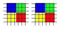
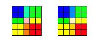
Figure 4.6 (a) The black
grid represents the CCD array, and (b) the results of sampling.
Although
the results seem quite alarming, it should be noted that the grids were
exaggerated for clarity. Moreover, the majority of the cells are not affected
by the boundaries, meaning that any color spot with a radius above a certain
threshold would be represented in the same fashion in both cameras.
Algorithm
Figure
4.7 presents an overview of the proposed correspondence algorithm, which
was implemented using an experimental MATLAB® code. The essential steps
of the algorithm are detailed and discussed in the following section. Further
details are available in the documented code (Appendix B).
Figure 4.7 A
Flow Chart of the color correspondence algorithm
Lowering Color Discrimination
Theoretically,
the possible combinations of 255 red, 255 green, and 255 blue colors are
16 581 375. If a smaller set of colors is to be used, then every
d
colors will be mapped into a single new color; thereby dividing the overall
number of colors by d. This step is useful to act against noise
introduced during the acquisition of the image. Figure 4.8 shows a histogram
of the difference between two images taken successively from the
same viewpoint. This observed discrepancy is be caused by internal noise,
light variations, etc ...
Figure4.8 The maximum
value of the histogram is 3; therefore, if the color discrimination is
lowered by 3, the two image become identical.
Removing Background Colors
Any
pixel that has a gray level value below a certain threshold is considered
as a background color. Background colors are discarded from the analysis
to speed up the correspondence process. These usually represent 30-40%
of the image. Consequently, for the actual implementation of the algorithm,
it is necessary to have the vertebra body surrounded by black clothing.
Insuring a Good Discrimination
When
two pixels of the same color are within a certain threshold on the same
image, it is not clear which one should be used for correspondence with
the other image. Such sets of pairs must be eliminated. This step is carried
out by checking for points of a similar color inside the epipolar regions
of each image.
Examples
A low-resolution (64´48) example is show in Figure 4.9, where the
correlation function used assumes a parallel configuration with the cameras
on top of each other. The white + represents a background color, the black
+ a color match and thus a candidate for a correspondence match, and the
black * a correspondence point. The results are overlaid on the upper image.
Figure 4.9 Candidates
= 140 , Matches = 102.
Figure
4.10 shows the results with a lower color discrimination.
Figure 4.10 Candidates=
223, Matches = 55.
Figure
4.11 shows the results for a larger correlation window.

Figure 4.11 Candidates
= 140, Matches = 62.
Efficiency and Challenges
The
efficiency of the proposed algorithm is now addressed, along with a presentation
of its main advantages and drawbacks.
Efficiency
The
efficiency of the algorithm heavily depends on the quality of the acquired
images. In a typical situation, the background represents at least 30%,
and the colors are well spread over the image and the spectrum. The efficiency
will then be equal to O(m.n.lg(m.n)),
where m and n
are the image dimensions and lg is the binary logarithmic. This
measure is equal to the general sorting efficiency, where the sorting of
the color represents the largest loop in the algorithm.
Drawbacks
The
main drawback of the proposed algorithm is its dependency on the white
color of the bone and on its shape. The first problem is of no concern
in orthopedic interventions. However, the second problem may occur other
parts of the body, such as the femur or the knee. In such cases, the light
has to be artificially varied over the surface. Moreover, different images
can be simultaneously used under different illumination conditions.